Introduction
Every sensor measurement recorded during a flight test program depends on one thing: a telemetry signal reaching the ground station intact. Without it, there's no real-time safety monitoring, no post-flight analysis, and no recoverable test data.
Yet telemetry signals are frequently treated as background infrastructure — assumed reliable until a failure proves otherwise. When a frame sync failure wipes out an hour of structural load data, or a spectrum violation shuts down range operations, the cost is immediate and sometimes unrecoverable.
This guide covers what telemetry signals actually are, how they're characterized, what governs their quality, and where engineers commonly go wrong.
Whether you're specifying a new flight test instrumentation system or troubleshooting a link that's underperforming in the field, the fundamentals here apply.
Key Takeaways
- Telemetry signals are RF-modulated carriers that encode digitized sensor data and transmit it from an airborne vehicle to a ground station in real time
- Signal quality is measured by Bit Error Rate (BER) and Eb/No — not signal strength alone
- PCM/FM and SOQPSK-TG are the dominant modulation formats at US federal test ranges
- L-band and S-band are the primary frequency allocations for aeronautical telemetry
- IRIG 106-24 (2024) governs RF transmission standards, PCM frame formats, and TMATS configuration
- Out-of-spec operation from interference, antenna misalignment, or bad frame configuration causes sync loss and unrecoverable data gaps
What Telemetry Signals Represent in Aeronautical Flight Test
A telemetry signal is an RF-modulated carrier that encodes digitized sensor measurements acquired from onboard instrumentation and transmits them across the air-ground link to receiving equipment for demodulation, decommutation, and analysis.
That definition matters because it clarifies where the signal sits in the architecture. It's the output of the airborne transmitter and the input to the ground station's RF front-end. It carries frame-structured PCM data streams organized per IRIG 106 standards, the telemetry standard maintained by the Range Commanders Council for interoperability at RCC member ranges.
From Sensor Output to RF Carrier
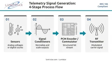
A telemetry signal is not the same as a raw sensor output. The distinction:
- Sensors produce analog voltages or digital counts (temperature, pressure, acceleration)
- Signal conditioners normalize and scale those outputs
- The PCM encoder/commutator packages multiple sensor channels into a structured bit stream
- The RF transmitter modulates that bit stream onto a carrier frequency — producing the telemetry signal
The signal is a design-constrained operating variable. Its frequency, power, bandwidth, and modulation are actively selected during system design to meet range, data rate, and regulatory requirements. Each parameter is a deliberate engineering choice, not a factory default.
The Ground Station Side
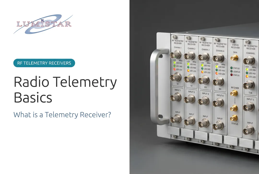
At the receiving end, Lumistar's LS-28-DRSM Series handles the full chain from RF front-end through decommutation in a single modular unit — dual-channel reception across up to six frequency bands (200 MHz to 7 GHz), multi-mode demodulation, bit synchronization, and optional decommutation with UDP data output.
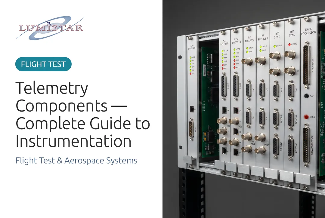
For programs that need those functions separated, Lumistar offers dedicated components for each stage:
- LS-35-R IF Receiver — demodulation
- LS-45 Series — bit synchronization
- LS-50-D / LS-68-M Series — frame sync and decommutation
Types and Operating Parameters of Telemetry Signals
Telemetry signals in aeronautical flight test are defined by four parameters: carrier frequency band, modulation scheme, data rate, and authorized power level. All are governed by IRIG 106 Chapter 2 and applicable spectrum regulations — primarily the NTIA Manual of Regulations and Procedures for Federal Radio Frequency Management, incorporated by reference at 47 CFR 300.1.
Carrier Frequency Bands
Three primary bands are used in aeronautical telemetry:
| Band | Frequency Range | Characteristics |
|---|---|---|
| L-band | 1435–1535 MHz | Better propagation, lower atmospheric loss; NTIA describes use here as "vital and extensive" for flight test |
| S-band | 2200–2290 MHz | Widely used at US federal ranges; good balance of propagation and bandwidth |
| C-band | 4400–4940 MHz | More available bandwidth; greater rain fade susceptibility, requires precise antenna pointing |
Frequency selection is a regulatory constraint. Access is coordinated through the NTIA frequency assignment process, with range-level coordination governed by RCC 700-17. L-band and S-band dominate at US federal test ranges.
Modulation Schemes
IRIG 106 Chapter 2 specifies several waveforms, each with distinct tradeoffs between spectral efficiency and implementation complexity:
| Waveform | Description | Key Tradeoff |
|---|---|---|
| PCM/FM | PCM bit stream frequency-modulates the carrier | Robust, simple implementation; spectrally inefficient |
| SOQPSK-TG | Shaped Offset QPSK (Tier I/II ARTM waveform) | ~50% bandwidth reduction vs. PCM/FM; preferred under L-band congestion |
| BPSK / QPSK | Phase-shift keying variants | Supported for programs with specific demodulator compatibility requirements |
| OQPSK / Multi-H CPM | Additional IRIG 106-specified formats | Used in specialized range or program configurations |
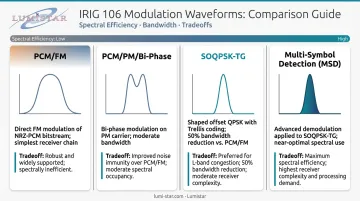
PCM/FM remains common at ranges where legacy ground equipment is already fielded. SOQPSK-TG has become the preferred waveform where range authorities enforce tighter occupied bandwidth limits, particularly in the congested 1435–1535 MHz L-band.
Data Rate and Bandwidth
Aeronautical telemetry links typically operate from sub-1 Mbps for simple instrumentation programs up to 10+ Mbps for high-density test configurations. Occupied bandwidth is a function of data rate and modulation — IRIG 106 Chapter 2 defines spectral mask requirements that constrain how much spectrum a signal may occupy at a given data rate.
Lumistar's hardware covers this range across the signal chain. The LS-28-DRSM demodulator supports PCM/FM, SOQPSK-TG, BPSK, QPSK, OQPSK, Multi-H CPM, and other waveforms at data rates up to 60 Mbps. Bit synchronizers support 100 bps to 45 Mbps for NRZ codes, and the LS-50-D decommutator handles inputs from 64 bps to 20 Mbps, covering the full operational range.
Key Technical Properties of Telemetry Signals
Beyond frequency and modulation, signal performance comes down to four interdependent properties: link budget, bit error rate, signal stability, and polarization. Each is a system-level variable.
Link Budget and Received Signal Strength
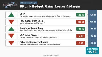
The link budget accounts for every gain and loss in the RF path from transmitter output to demodulator input. Key parameters:
- EIRP — Effective Isotropic Radiated Power of the airborne transmitter
- Free-space path loss — scales with range squared and frequency squared
- Ground antenna gain — directly offsets path loss
- LNA noise figure — sets the receiver noise floor
- Cable and connector losses — cumulative, often underestimated
Link margin is the difference between the received Eb/No (energy per bit to noise density ratio) and the minimum Eb/No required for acceptable BER at the selected modulation. Positive link margin is the fundamental requirement for data recovery. Think of it as a buffer: a narrow margin leaves little tolerance for real-world degradation.
Lumistar's LS-28-DRSM includes AGC outputs with 120 dB dynamic range and +/- 1 dB linearity, giving operators continuous visibility into received signal strength during operations.
Bit Error Rate and Eb/No
BER — the fraction of received bits in error — is the operational quality metric for a telemetry link. Signal strength (RSSI) alone doesn't tell you whether data is usable.
A signal can be well above the noise floor and still exhibit high BER due to phase noise, interference, or demodulator misalignment. What matters is whether Eb/No clears the demodulation threshold for the selected modulation scheme.
The acceptable BER threshold in flight test telemetry is commonly cited at 10⁻⁶ or better, per RCC 119-06 telemetry performance guidance. As Eb/No drops below the demodulator threshold, BER degrades non-linearly: a small drop in margin produces a disproportionately large increase in errors, a behavior known as the waterfall region.
Lumistar's LS-45 bit synchronizers and LS-35-R IF receiver include built-in BER measurement. The LS-28-DRSM Series incorporates a BER reader as a standard feature, surfacing this metric directly to the operator without requiring external test equipment.
Signal Stability, Polarization, and Antenna Tracking
Aircraft maneuvers — banking turns, pitch pulls, rolling sequences — rotate airborne antennas relative to the ground station. Signal amplitude and phase stability are directly affected.
Polarization mismatch is a frequently overlooked link budget term. When airborne and ground antenna polarizations are misaligned, received signal strength drops. This loss compounds with other degradations and can push a marginal link below threshold during dynamic flight phases.
Lumistar's LS-27-M Series tracking receivers are specifically designed for auto-tracking antenna systems, providing programmable AGC and AM outputs with five selectable time constants (0.1 to 1000 ms) that antenna controllers use to maintain pointing lock. The LS-28-DRSM includes the same independent dual-channel tracking receiver function.
How Telemetry Signals Are Specified, Formatted, and Validated
RF parameters define how a telemetry signal travels — but the data it carries must also be structured so ground equipment can decommutate the bit stream into individual engineering parameters.
The IRIG 106 Standard Structure
IRIG 106-24, published October 2024 by the Range Commanders Council, governs this end-to-end:
- Chapter 2 — RF transmission standards: modulation, bandwidth, and power limits
- Chapter 4 — PCM bit stream format: frame structure, sync word patterns, word length
- Chapter 9 — TMATS (Telemetry Attributes Transfer Standard): the universal configuration document defining measurand names, bit locations, units, and calibration
TMATS serves as the source-of-truth file that configures both airborne and ground station equipment from one consistent definition. Lumistar's ground station products comply with IRIG 106 requirements, supporting IRIG 106 Chapter 4 Class I and Class II compliance across the LS-18, LS-28, LS-50-D, and LS-68-M Series.
Pre-Flight Validation
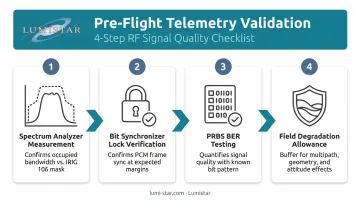
Verifying signal quality before live flight involves multiple steps:
- Spectrum analyzer measurement — confirms occupied bandwidth complies with the IRIG 106 spectral mask for the selected modulation and data rate
- Bit synchronizer lock verification — confirms the PCM frame structure achieves sync lock at expected margins
- PRBS (pseudo-random bit sequence) BER testing — quantifies signal quality using a known bit pattern; Lumistar's LS-18-P1 supports PRN pattern generation with internal BER loopback testing at rates from 1000 bps to 60 Mbps
- Field degradation allowance — bench-verified margin must include a buffer for real-world effects absent from lab conditions: actual range geometry, aircraft attitude, multipath, and antenna shadowing
Implications of Signal Degradation and Out-of-Spec Transmission
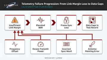
The failure chain is direct: insufficient link margin → elevated BER → frame sync loss → corrupted or missing parameter values → data gaps in the test record.
In a safety-critical flight test program, that chain can mean a test abort, a repeat sortie, or — in the worst case — inability to reconstruct what happened during a failure event.
Specific Failure Modes
| Out-of-Spec Condition | Failure Mode |
|---|---|
| Frequency offset | Demodulator loses phase lock; signal appears present but produces no valid data |
| Excessive transmit power | Spectrum authorization violation; interference to other range users |
| Incorrect sync word or word length | Frame synchronizer never achieves lock; entire data stream is unreadable |
| Antenna pointing error during maneuver | Polarization mismatch + reduced antenna gain compound to push Eb/No below threshold |
When any of these conditions occur mid-flight, real-time decoding may fail entirely. Post-flight recovery then depends on having a wideband RF recording of the raw spectrum. Lumistar's LS-29-R2 Series RF Recording and Playback System captures up to 200 MHz of RF spectrum with 120 dB instantaneous dynamic range, enabling engineers to replay degraded segments with adjusted demodulation parameters and attempt reconstruction of data that was unreadable in real time.
Regulatory Consequences
Unauthorized frequency use or excess occupied bandwidth at US test ranges carries operational consequences. The NTIA Manual (incorporated at 47 CFR 300.1) is the governing framework for federal spectrum management; range-level coordination operates under RCC 700-17. Operating outside assigned parameters doesn't just degrade data quality — it can result in range authorities suspending test operations entirely.
Common Misinterpretations of Telemetry Signals in Practice
Two errors appear repeatedly, even among experienced engineers:
1. Using RSSI as a proxy for data quality. A received signal that appears strong — well above the noise floor — can still produce unacceptable BER if it's below the Eb/No threshold for the selected modulation. The metric that matters is margin relative to the demodulation threshold, not absolute received power in dBm. Lumistar's integrated BER readers are built to make this distinction visible during operations.
2. Assuming lab-validated configurations translate directly to field operation. Bench testing confirms that the PCM format achieves frame sync lock under ideal conditions. It doesn't replicate the conditions found in the field:
- Actual range geometry and varying slant ranges
- Aircraft attitude changes affecting antenna orientation
- Antenna shadowing from airframe structure
- Multipath reflections from terrain
A format with zero margin in the lab will intermittently lose sync in flight.
There's a third trap worth flagging: confusing nominal bit rate with actual throughput. Subcommutation overhead, sync words, and subframe identifiers consume bandwidth — a 5 Mbps link doesn't deliver 5 Mbps of engineering parameter data.
Conclusion
Telemetry signals are a governed design variable — not a default setting.
Frequency band, modulation scheme, data rate, and link margin are engineering decisions with regulatory, technical, and operational consequences. Treating them as infrastructure that configures itself leads to test failures that are expensive, sometimes irreversible, and avoidable.
Key principles to carry forward:
- Signal quality is determined end-to-end, from the PCM encoder through the RF transmitter to the ground station demodulator
- Link margin must account for real range conditions, not ideal assumptions
- IRIG 106-24 and the NTIA Manual define the framework; they don't replace engineering judgment
- Modulation and data rate decisions made early in program design constrain every stage that follows
The published standards provide the framework. Applying that framework to actual range conditions — accounting for antenna geometry, interference environment, and mission-specific data requirements — is where programs succeed or fall short. Engineers working with purpose-built telemetry hardware that covers the full signal chain have a material advantage in closing that gap.
Frequently Asked Questions
What is the telemetry system used for?
Telemetry systems remotely measure and transmit data from aircraft, missiles, and spacecraft to a ground station in real time. Engineers use this live data to monitor performance, structural behavior, and safety-critical parameters during flight — without relying solely on recovered onboard recordings.
What can telemetry detect?
Telemetry systems capture any sensor output that can be digitized into a PCM data stream: structural loads, vibration, temperature, pressure, acceleration, control surface positions, engine parameters, fuel flow, GPS position, and more. The measurand set is defined by the instrumentation design and TMATS configuration.
What are the different types of telemetry systems?
Aeronautical flight test telemetry uses IRIG 106-based PCM systems. Space telemetry uses CCSDS-based standards. Other domains — medical, industrial — use their own protocols and frequency bands. Each system is designed for its specific operating environment and data requirements.
What are the components of a telemetry system?
The airborne segment includes sensors, signal conditioners, a PCM encoder, RF transmitter, and antenna. The ground segment covers the receiving antenna, low-noise amplifier, RF receiver, demodulator, bit synchronizer, frame synchronizer, and decommutator. Lumistar's ground station products span the complete ground-side chain, from antenna to decommutator.
Is telemetry the same as SCADA?
No. SCADA (Supervisory Control and Data Acquisition) is a broader architecture that includes control commands and supervisory logic alongside data acquisition. Telemetry refers specifically to remote measurement and one-way data transmission. SCADA uses telemetry as one component of a larger sense-analyze-command loop.
How much does telemetry cost?
Cost varies significantly based on system complexity, channel count, frequency bands, and required modulation formats. Lumistar's modular product architecture allows cost-effective scaling from individual components to complete integrated ground stations. Contact Lumistar at sales@lumistar.net or 760-431-2181 for a configuration-specific quote.