For aeronautical flight test professionals, understanding how these systems are built, how data moves through them, and what standards govern them isn't optional background knowledge. It's the foundation of the entire discipline. This guide covers how satellite telemetry systems function, what components they consist of, how data gets tracked and processed in real time, and why IRIG 106 defines the rules of the road.
Key Takeaways
- Telemetry is the automatic collection and wireless transmission of measurement data from a remote vehicle to a ground receiving station
- A complete system spans RF reception, demodulation, bit synchronization, decommutation, and data recording
- Modern flight test aircraft can stream up to 250,000 parameters simultaneously — making ground processing infrastructure critical
- IRIG 106 governs aeronautical and range telemetry compliance across U.S. test programs
- Ground station hardware has shrunk from 250 kg rack systems to sub-1 kg handheld units — with no loss in processing performance
What Is Satellite Telemetry and How Does It Work?
Telemetry is the automatic collection of physical measurements at a remote location and their wireless transmission to receiving equipment for monitoring and analysis. The word itself combines the Greek roots tele (far) and metron (measure) — but in flight test, the definition is best understood through what it does, not where it comes from.
In aeronautical and aerospace contexts, "satellite telemetry" can mean different things depending on context. For orbital programs, it refers to data downlinked from spacecraft. For flight test, it describes real-time RF data transmission from an airborne test vehicle (aircraft, missile, or UAV) to a ground station, sometimes via relay assets including satellites or airborne relay platforms.
The Core Transmission Principle
Onboard sensors measure physical parameters (temperature, pressure, acceleration, fuel flow, structural strain) and feed that data into a flight test instrumentation (FTI) system. The FTI encodes those measurements, typically using Pulse Code Modulation (PCM) per IRIG 106, then a transmitter modulates the encoded data onto an RF carrier. A ground antenna receives it.
Two transmission modes are used in flight test:
- Direct-to-ground: The test vehicle transmits directly to a ground receiving antenna within line-of-sight range — the standard mode for most conventional flight test programs
- Relay-assisted: Data routes through airborne relay platforms or satellite links to extend range beyond line-of-sight — used when missions exceed the geographic reach of fixed ground sites
The Edwards AFB 5790 Telemetry Site illustrates this in practice: ground telemetry sites relay aircraft test data to engineers in control rooms for real-time analysis.
Telemetry vs. Telecommand
Telemetry (data flowing from vehicle to ground) is the counterpart to telecommand (instructions flowing from ground to vehicle). Together they form the TT&C framework (Telemetry, Tracking, and Command) familiar to both spacecraft operations and flight test programs. For aeronautical flight test, the telemetry downlink carries the primary engineering and safety data.
Why Telemetry Is Critical in Flight Test
In flight test, the vehicle under evaluation may be pushed to structural limits, destroyed, or operated in conditions where onboard recording is inaccessible. Real-time telemetry gives ground engineers direct visibility into vehicle health as events unfold — there's no equivalent substitute.
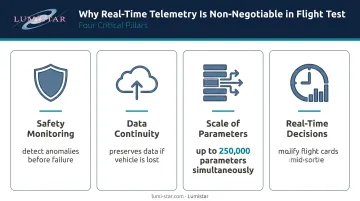
Several factors make that link non-negotiable:
- Safety monitoring: Engineers can detect anomalies and abort a test before catastrophic failure
- Data continuity: If the vehicle is lost, telemetry preserves the data that would otherwise be unrecoverable
- Scale of parameters: F-35 flight test at Edwards AFB routinely transmits up to 250,000 parameters simultaneously, requiring substantial ground processing infrastructure to handle the load
- Real-time decisions: Test directors can modify flight cards mid-sortie based on live data rather than waiting for post-flight analysis
Key Components of a Satellite Telemetry System
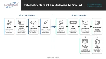
Data doesn't jump from sensor to screen. It moves through a sequence of hardware and software components across two distinct domains: the airborne segment (onboard the vehicle) and the ground segment (at the receiving station).
Airborne Segment: Sensors, Encoders, and Transmitters
The airborne segment consists of:
- Sensors that measure physical parameters (pressure transducers, accelerometers, thermocouples, strain gauges)
- FTI system that samples, conditions, and encodes those signals — typically using PCM per IRIG 106, which defines PCM telemetry as a serial bit stream of binary-coded, time-division multiplexed words
- Transmitter and antenna that modulate the encoded data onto an RF carrier and broadcast it
PCM encoding standards ensure the ground system can correctly interpret what it receives, enabling interoperability across programs and test ranges.
Lumistar's airborne products, including the LS-28-DRSM and LS-26 Series, are rated for aircraft installation and support multi-band RF reception for chase plane and relay applications, with data re-transmission capabilities for air-to-ground workflows.
Ground Segment: Antennas, Receivers, and Bit Synchronizers
Once the signal leaves the vehicle, the ground receiving chain takes over:
- Tracking antenna (fixed, portable, or vehicle-mounted) acquires the RF signal from the test vehicle
- RF receiver demodulates the signal and outputs the baseband data stream
- Bit synchronizer recovers the clock and data bits from that stream for downstream processing
Antenna tracking accuracy and receiver sensitivity are not minor details. A missed signal during a critical test maneuver means permanently lost data. Lumistar's receivers support RF bands from 200 MHz to 6 GHz — covering Lower L-Band (1435–1540 MHz), S-band (2200–2400 MHz), and C-band — with an AGC range exceeding 120 dB.
Signal Processing: Decommutation and Data Processing
Decommutation is the process of separating a multiplexed PCM data stream back into its individual parameter channels. A decommutator — hardware or software — uses the pre-flight frame structure configuration to assign each bit to the correct engineering parameter.
At this stage, the processing system also applies:
- Engineering unit conversions (raw counts → engineering values)
- Limits checking against pre-defined thresholds
- IRIG time-tagging for post-flight correlation
Data Recording, Display, and Archiving
Processed data feeds two parallel outputs simultaneously:
- Real-time display systems — trend plots, time-history displays, limit alarm panels — for engineers monitoring the active flight
- Recording systems — high-capacity storage for post-flight analysis, data reduction, and archiving
Lumistar's product line spans this entire chain. The LS-84-R4 delivers a complete RF-to-display-to-archive solution in a 4U rack, while the LS-68 Series Digital Processing Engine consolidates bit synchronization, decommutation, display, and recording into a single compact unit. The LDPS software handles real-time parameter visualization at the display stage.
How Telemetry Data Is Tracked and Processed in Real Time
Real-time telemetry monitoring isn't passive. Engineers are making safety-of-flight decisions based on what the data reveals — often within seconds of receiving it.
Anomaly Detection and Limit Monitoring
Before each flight, engineers load pre-defined parameter limits into the display and processing system. During the mission, any parameter exceeding its threshold triggers a visual or audible alarm. The engineering team assesses the condition and, if necessary, calls for a test abort or mission modification.
This is only possible because the telemetry system delivers data with low enough latency to be actionable. Delays in the data chain — dropped packets, processing bottlenecks, or signal dropouts — directly compromise the safety function that real-time telemetry provides.
Data Synchronization and Time Correlation
Precise time-tagging is what makes multi-source data analysis possible after the flight. IRIG-B time code generators establish time correlation between real-time ground data and data recorded onboard the test vehicle, enabling engineers to reconstruct the exact sequence of events.
IRIG 106 Chapter 21 defines the Telemetry Network Standard (TmNS), which uses an IP network architecture for distributing telemetry data across range infrastructure — enabling synchronized data access across multiple ground stations and analysis systems.
To support these standards in practice, Lumistar systems are compatible with IRIG Time Code formats A, B, and G, as well as PTP IEEE 1588 Precision Time Protocol for network-synchronized installations.
Post-Flight Data Reduction and Analysis
After landing, archived telemetry undergoes formal data reduction:
- Engineering unit calibrations are verified
- Parameters are filtered and smoothed as needed
- Results are compared against pre-flight predictions and simulation models
This phase often surfaces slower-developing trends that real-time monitoring misses. The quality of post-flight analysis depends directly on the integrity of the recorded data — gaps or corruption in the archive can make it impossible to reconstruct anomalies that only become visible hours after landing.
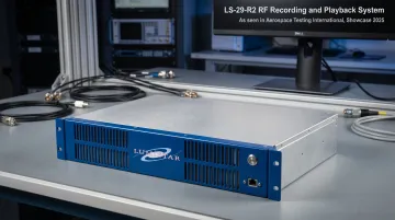
Lumistar's LS-29-R2 RF Recording and Playback System supports this workflow with 120 dB instantaneous dynamic range, ±20 nanosecond timing accuracy, and the flexibility to play back recorded signals at a different center frequency than they were recorded — useful for testing ground station configurations post-flight.
Telemetry Standards: IRIG 106 and Why They Matter
IRIG Standard 106-24IRIG Standard 106-24, published October 2024 by the Range Commanders Council (RCC), is the current governing standard for aeronautical and range telemetry systems in the United States. Its stated purpose: to foster compatibility of telemetry transmitting, receiving, and signal-processing equipment at RCC member ranges, and to ensure efficient spectrum use and interoperability across facilities.
What IRIG 106 Covers
| Area | IRIG 106-24 Coverage |
|---|---|
| RF systems | Chapter 2: Transmitter and Receiver Systems |
| PCM encoding | Chapter 4: Pulse Code Modulation Standards |
| Data formats | Packet Telemetry, Digital Data Bus Acquisition, Recorder Data Packet Format |
| Networked telemetry | Chapters 21–28: Telemetry Network Standard (TmNS) |
Why Compliance Matters Operationally
For any program operating at a federal test range, IRIG 106 compliance is not optional. Member ranges listed in IRIG 106-24 include Patuxent River NAS, White Sands Test Center, Redstone Test Center, Reagan Test Site, and others. Non-compliance creates integration problems, schedule delays, and unplanned costs.
Compliance ensures:
- Interoperability between airborne instrumentation and ground stations from different vendors
- Compatibility with range infrastructure without custom integration work
- Consistent data formats that support cross-range and multi-program data sharing
Lumistar's products support IRIG 106 Chapter 4 Class I and Class II data formats, ARTM Tier 0, Tier 1, and Tier 2 modulation standards, and optional LDPC forward error correction per IRIG 106 specification — covering all six defined LDPC codes. That coverage spans the full scope of federal test range requirements without program-specific customization.
IRIG 106 governs aeronautical flight test. For orbital and deep-space programs, CCSDS (Consultative Committee for Space Data Systems) fills the equivalent role — but for anything operating at a federal range, IRIG 106 is the standard that matters.
Modern Trends Shaping Satellite Telemetry Systems
Miniaturization and Portable Ground Stations
Less than 20 years ago, a typical flight test telemetry ground station stood 8 feet tall, weighed 250 kg, and consumed several thousand watts. The same functional capability now fits in a handheld enclosure.
Lumistar's LS-28-DRSM measures 6.00" × 4.00" × 1.67", weighs under 1 kg, and consumes approximately 40–50 watts — while delivering dual-channel RF reception, diversity combining, multi-mode demodulation, data recording, and TMoIP Ethernet streaming in one unit. The portable LS-28-DRSM-P1 lunchbox configuration adds battery operation (up to 10 hours), IP-67 waterproofing, and salt-water flotation for shipboard deployment.
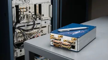
This shift matters practically: mobile test ranges, ship-based operations, and austere forward locations can now run full-capability telemetry operations without fixed infrastructure.
Firmware-Configurable Hardware Platforms
Modern telemetry hardware increasingly uses firmware-based architectures that allow a single physical unit to support multiple waveforms, data rates, and modulation schemes through software updates rather than hardware replacement.
The LS-28-DRSM exemplifies this approach. Supported modulation formats are implemented as firmware personalities and updated in the field:
- PCM/FM, SOQPSK-TG, Multi-H CPM, BPSK, QPSK, and additional formats
- New waveforms deployed via firmware update — no hardware swap required
- The LS-68-M reconfigures between frame synchronizers, decommutators, and PCM simulators through licensing options alone
For programs with shifting test requirements, this directly reduces lifecycle costs and procurement lead times — without waiting on hardware replacement cycles.
IP-Based Data Distribution
IRIG 106-24 Chapters 21–28 define the Telemetry Network Standard (TmNS), formalizing IP-based transport as part of the range telemetry architecture. Standard IP transport delivers practical capabilities across distributed test programs:
- Remote real-time monitoring from geographically separated facilities
- Collaborative data review across multiple analysis teams simultaneously
- Integration with modern analytics and visualization tools
Lumistar's systems support TMoIP UDP multicast output across the product line, with Gigabit Ethernet interfaces carrying telemetry data from RF reception through to networked display clients.
Frequently Asked Questions
What is the difference between satellite telemetry and flight test telemetry?
Satellite telemetry refers to data downlinked from orbital spacecraft, governed primarily by CCSDS standards. Flight test telemetry refers to real-time RF data transmitted from an airborne test vehicle to a ground station, governed by IRIG 106 for U.S. aeronautical programs. Both share common RF and PCM encoding principles, though their standards, frequency allocations, and operational environments differ significantly.
What does IRIG 106 govern in a telemetry system?
IRIG 106 is the U.S. range telemetry standard that defines PCM data formats, RF frequency bands, modulation schemes, recorder formats, and ground system interface requirements, ensuring interoperability across federal test ranges. The current edition is IRIG 106-24, published October 2024.
What components make up a ground telemetry receiving station?
The core chain runs: tracking antenna → RF receiver → bit synchronizer → decommutator/data processor → display system → data recorder. This sequence converts a raw RF signal into time-tagged, engineering-unit-calibrated parameter data ready for analysis.
How is telemetry data transmitted from an aircraft to the ground?
Onboard sensors feed a flight test instrumentation system that encodes data via PCM and modulates it onto an RF carrier. An onboard antenna transmits the signal; a directional ground antenna receives it within line-of-sight range, or relay assets extend coverage for beyond-line-of-sight missions.
What frequency bands are commonly used in aeronautical telemetry?
U.S. aeronautical telemetry uses L-band (1435–1535 MHz) and S-band allocations including 2200–2290 MHz and upper S-band around 2310–2395 MHz, as defined in IRIG 106 Chapter 2 and coordinated with the NTIA's federal frequency management framework.
How has miniaturization changed modern telemetry ground stations?
Firmware-configurable hardware and digital RF components have reduced ground stations from 8-foot, 250 kg rack systems to sub-1 kg handheld units under 50 watts. This size reduction makes portable, vehicle-mounted, airborne, and ship-based deployments practical where legacy infrastructure was never an option.