Frame synchronization solves that problem. It's the process that transforms a raw serial bit stream into a structured, usable data record — locating the repeating boundaries that tell your decommutator exactly which bit position carries which engineering parameter.
This guide covers what frame synchronization is, how it works within PCM telemetry signal chains, the framing schemes defined by IRIG 106 standards, common failure modes, and the configuration practices that keep sync stable through a demanding flight test mission.
Key Takeaways
- Frame sync locates repeating sync word patterns within a PCM bit stream to establish frame boundaries
- Per RCC Standard 106-24 Chapter 4, sync words must be 16–33 bits; standard patterns include the 16-bit binary
1110101110010000(0xEB90) - Frame synchronizers operate in three states: search, verify, and lock, each with configurable transition thresholds
- Without frame sync, decommutation is impossible; even brief lock loss corrupts your data record
- Mismatched parameters between the airborne encoder and ground station synchronizer are the most preventable cause of frame sync failure
What Is Frame Synchronization?
In PCM telemetry, data travels as a serial bit stream of binary-coded, time-division-multiplexed words — a format defined in RCC Standard 106-24 Chapter 4. That stream has no inherent markers telling a receiver where one group of parameters ends and another begins. Frame synchronization is the process that recovers those boundaries.
The Structure of a PCM Frame
RCC 106-24 defines a minor frame as the data sequence from the beginning of one minor-frame synchronization pattern to the beginning of the next. Every minor frame starts with a sync word (a fixed, pre-agreed binary pattern assigned as word zero), followed by payload data words numbered sequentially from word one onward.
A major frame (or superframe) is the number of minor frames required to include one occurrence of every word in the format, enabling subcommutated parameters that update less frequently than every minor frame.
The sync word is what makes frame boundaries detectable. The receiver searches for its recurrence at consistent intervals and, once confirmed, knows where every parameter slot falls within every subsequent frame.
Telemetry Frame Sync vs. Video Genlock
These terms get confused, but the technologies are unrelated:
- Genlock (SMPTE broadcast standards): aligns multiple video signal clocks to a common timing reference for broadcast production
- PCM frame synchronization: locates fixed binary patterns within a serial data stream to recover data structure for telemetry
Applying broadcast-oriented assumptions to a PCM receiver configuration — or vice versa — leads to fundamentally incorrect setup.
How Frame Synchronization Works in Telemetry Systems
A frame synchronizer sits downstream of the bit synchronizer, receiving its recovered clock and data outputs. Its job: scan the incoming bit stream for the known sync word and confirm that word recurs at the expected frame interval.
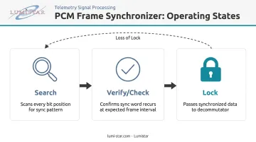
The Three Operating States
Per the Telemetry Applications Handbook, RCC 119-06, frame synchronizers typically operate across three states:
- Search — The synchronizer scans every bit position, comparing incoming data against the known sync pattern. False matches are possible here, particularly for shorter patterns.
- Verify/Check — A candidate sync position has been found. The synchronizer confirms it by checking that the sync word reappears at the predicted frame interval for a configurable number of consecutive frames before declaring lock.
- Lock — The sync position is confirmed. The synchronizer tracks the pattern at each expected frame boundary and passes synchronized data to the decommutator.
Lock and Loss-of-Lock Thresholds
The number of consecutive correct patterns required to transition from verify to lock, and the number of consecutive failures that trigger a return to search, are configurable parameters — not fixed IRIG standard values. RCC 119-06 treats these as implementation decisions tuned to the operating environment.
Threshold selection involves a direct tradeoff between speed and stability:
- Tighter thresholds (fewer consecutive frames to lock, fewer misses before losing lock) react quickly but risk spurious dropouts from transient noise
- Looser thresholds tolerate noise better but slow acquisition and delay recognition of genuine sync loss
For noisy links, RCC 119-06 notes that allowing some errors within the sync pattern itself — and requiring more than one bad pattern before declaring loss of lock — can sustain reliable operation at degraded BER conditions.
Flywheel Operation
Production frame synchronizers maintain the last known frame timing for a defined number of frames before declaring loss of lock. This flywheel behavior prevents dropouts caused by transient interference — a momentary multipath spike or bit error cluster that would otherwise kick the synchronizer back to search mode unnecessarily. Lumistar's LS-50-D decommutator, for example, provides configurable sync error tolerance (0–15 bits selectable), allowing operators to tune exactly how many bit errors within a sync word the system will accept before flagging a miss — a key parameter for maintaining lock through degraded signal conditions.
Frame Synchronization Patterns and Framing Schemes
The sync word is the foundation of the entire frame structure, and its selection has real consequences — engineers who've chased a false-lock condition at altitude understand why pattern choice matters from the start.
IRIG 106 Sync Word Requirements
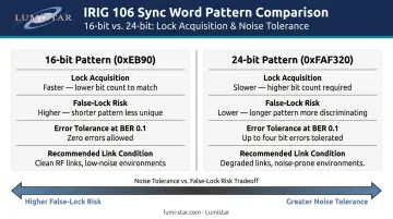
RCC 106-24 Section 4.3.2.a(3) specifies that the minor-frame sync pattern must be a fixed digital word between 16 and 33 consecutive bits in length. The standard also prohibits fragmented sync words — the pattern must occupy contiguous bit positions. Appendix 4-A of RCC 106-24 provides Table A-1, which lists recommended "Optimum Frame Synchronization Patterns for PCM Telemetry" across the full 16–33 bit range, selected by minimizing total false synchronization probability during the search phase.
Two commonly used patterns from that table:
| Length | Binary Pattern (Transmission Order) | Hex Equivalent |
|---|---|---|
| 16-bit | 1110101110010000 |
0xEB90 |
| 24-bit | 111110101111001100100000 |
0xFAF320 |
Note: RCC 106-24 Table A-1 lists these in binary. The hex values are conversions from that binary transmission order.
Longer patterns reduce false-lock probability during search. A 16-bit pattern in a 4,000-bit frame requires zero allowed errors to keep false synchronization probability below 0.00005. A 24-bit pattern at BER 0.1 requires up to four allowed errors to achieve 0.9 probability of detection. The pattern length you choose is a direct tradeoff between false-lock risk and noise tolerance.
Minor Frames, Major Frames, and Subframe IDs
Frame size limits under RCC 106-24:
- Class I minor frames: maximum 8,192 bits or 1,024 words
- Class II minor frames: maximum 16,384 bits
Individual minor frames group into a major frame (superframe). The standard method for tracking major frame position is a Subframe Identifier (SFID) counter — a counter located at a fixed position within every minor frame that increments sequentially, with its initial count marking the start of a new major frame. This second-level synchronization enables subcommutation, allowing infrequently sampled parameters to occupy a given word slot in only some minor frames.
Lumistar's LS-68-M series supports major frame lengths up to 65,536 minor frames and includes SFID counter modes (FCC, FAC, SFID, URC) for subframe synchronization.
CRC Verification as a Supplement
Some systems add CRC checking as a statistical confidence layer on top of sync word detection. When a CRC check word is used, RCC 106-24 Section 4.3.3 requires that it:
- Be placed at the end of each minor frame
- Occupy the same position in every frame
- Be calculated in bit-transmit order
Lumistar's LS-50-D and LS-50-E decommutators include a CRC16/CCITT checker that works alongside sync pattern detection. This catches corrupted frames that pass sync word verification but carry invalid data — a failure mode that sync detection alone cannot flag.
Frame Synchronization in the Telemetry Signal Chain
The frame synchronizer occupies a specific position in the ground station chain: after the RF receiver and bit synchronizer, before the decommutator. Each stage depends on the one before it.
Why BER Upstream Matters
Frame sync quality is directly coupled to bit sync quality. A degraded RF link produces a higher bit error rate (BER) at the bit synchronizer output, which means more bit errors reaching the sync pattern matching logic. This forces longer lock acquisition times and more frequent lock losses.
RCC 118-25 identifies a severely errored second as any one-second interval with BER ≥ 1×10⁻⁵ — a useful threshold for understanding when frame sync stability becomes genuinely at risk. Once BER climbs toward that level, even longer sync patterns and generous error tolerance thresholds struggle to maintain stable lock.
Integrated Hardware Architecture
Lumistar's telemetry ground station equipment integrates bit synchronization and frame synchronization within a single platform, eliminating inter-stage cabling and configuration mismatches. The LS-68-M Series Digital Processing Engine provides bit sync, frame sync, and decommutation in one unit, available as a portable lunchbox (LS-68-M-P1) or 1U rack-mount (LS-68-R1). The LS-50-D and LS-50-E PCM decommutators support frame sync patterns up to 64 bits with selectable sync error tolerance, and accept an optional bit synchronizer daughterboard to create a fully integrated single-card solution.

Downstream Impact on Decommutation
That integrated architecture matters because the decommutator relies entirely on stable lock. Once frame sync is established, bit position N in every frame maps to a specific parameter, with the correct calibration and engineering unit conversion applied. A brief loss of lock corrupts that mapping entirely.
Even a few frames of lost sync can produce invalid engineering data that's difficult to distinguish from real exceedances — without cross-referencing sync lock/loss event logs against the data stream. Lumistar's systems include built-in BER readers and configurable diagnostic I/O to enable that real-time monitoring during flight.
Common Frame Sync Errors and How to Detect Them
Frame sync errors show up as gaps or corruption in the decommutated data record. The underlying failure can be a missed acquisition, a dropped lock mid-flight, or a false lock on non-sync data — each with different diagnostic signatures.
Root Causes
Per RCC 119-06 and RCC 118-25, documented causes include:
- High BER from weak RF signal, antenna dropout, or receiver tuning errors — the most common operational cause
- Single-bit slips that shift data position relative to the expected sync word location
- Multipath interference: specular or diffuse reflections that corrupt signal integrity at the receiver
- Plume attenuation and ducting, documented in RCC 119-06 as synchronization failure causes in aeronautical applications
- Configuration mismatches — frame length, sync word, or bit rate set differently between the airborne encoder and ground station synchronizer
- Antenna handover gaps or line-of-sight breaks that force a full re-acquisition cycle
Detection and Diagnosis
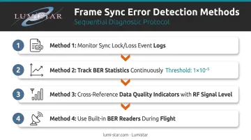
Knowing the causes narrows the search; the following methods let you catch and correlate failures in real time.
- Monitor sync lock/loss-of-lock event logs in real time — Lumistar systems provide configurable user-defined I/O pins that can signal lock state changes
- Track BER statistics continuously; degradation toward 1×10⁻⁵ predicts increasing sync instability before lock is fully lost
- Cross-reference data quality indicators in the decommutated stream with RF signal level data to correlate dropout timing with signal geometry
- Use built-in BER readers (standard on Lumistar LS-28-DRSM and LS-68-M series) during flight to catch degradation early
Best Practices for Frame Synchronization in Flight Test Telemetry
1. Choose sync words from IRIG 106 Table A-1 The patterns in RCC 106-24 Appendix 4-A were specifically selected to minimize false synchronization probability across the overlap portion of the search phase. Custom patterns can work, but you must verify autocorrelation properties independently before treating them as flight-ready.
2. Match pattern length to link quality expectations Longer patterns reduce false-lock risk but require looser error tolerance at high BER. Shorter patterns lock faster in clean conditions but are more vulnerable to accidental data matches. Test your chosen pattern length against the expected BER for your specific RF link geometry before committing to a flight configuration.
3. Tune lock/loss-of-lock thresholds to mission conditions Configure and validate these thresholds at the expected BER for your link — not just at ideal signal conditions. Two standards govern this validation process:
- RCC 119-06: Validate BER performance using a 2,047-bit pseudo-random sequence
- RCC 118-25: Require a minimum 30-minute equipment warm-up before RF subsystem validation testing
4. Conduct end-to-end parameter verification before every flight Confirm that frame length, sync word, bit rate, and PCM encoding format match exactly between the airborne PCM encoder and the ground station frame synchronizer. A single parameter mismatch between encoder and ground station will prevent frame lock regardless of signal quality. Lumistar's LS-18 series includes an internal BER reader and PRN pattern generator built specifically for this end-to-end loopback verification.
5. Never fragment the sync word RCC 106-24 Section 4.3.1.b prohibits fragmented sync patterns. The sync word must occupy contiguous bit positions within the minor frame — no exceptions.
Frequently Asked Questions
What does a frame sync do?
A frame synchronizer scans an incoming PCM bit stream for the recurrence of a known sync word pattern, identifies where each minor frame begins and ends, and passes that timing to the decommutator. Without it, the decommutator has no way to know which bit position carries which engineering parameter.
What is a frame sync error?
A frame sync error occurs when the synchronizer fails to find the expected sync word at the predicted frame interval — due to bit errors, a configuration mismatch, or a signal interruption. The result is lost lock and a gap or corrupted span in the decommutated telemetry record.
Should I sync every frame?
For raw single-channel recording, the bit stream is stored as-is without re-syncing. For real-time display, decommutation, or any multi-channel processing, frame synchronization must be maintained continuously — losing sync mid-mission means losing the data associated with those frames.
What is the difference between Genlock and frame sync?
Genlock is a broadcast/video term for locking multiple video signal clocks to a common reference under SMPTE standards. PCM telemetry frame synchronization is the process of detecting fixed binary sync patterns in a serial data stream to recover frame boundaries. They are unrelated technologies from different domains.
Is frame sync good?
Frame synchronization is the prerequisite for all downstream telemetry processing. Without it, decommutation cannot begin, engineering unit conversion cannot happen, and the data record is unusable.
What is synchronization in simple words?
Synchronization means aligning a receiver's internal timing with the transmitter's timing so both ends agree on when each piece of data starts and stops. In PCM telemetry, this happens at two levels: bit sync (recovering individual bit timing) and frame sync (locating the boundaries between groups of bits that form a complete frame).