IRIG-B exists precisely for these environments. Developed by the U.S. military's Inter-Range Instrumentation Group and formalized in 1960, it remains the dominant precision timing standard across defense, aerospace, and critical infrastructure — decades later and for good reason.
This guide covers what IRIG-B is, how it works, its format variants, real-world applications, and how it compares to network-based timing alternatives.
Key Takeaways
- IRIG-B is a hardware-based timecode standard that encodes precise time into a continuous serial signal distributed over dedicated wiring
- IRIG-B transmits 100 bits per second in a 1-second frame, encoding seconds, minutes, hours, and day of year in BCD format
- Format variants are identified by a letter-digit code (e.g., B122, B003) that specifies modulation type, carrier frequency, and data content
- Unmodulated IRIG-B delivers timing accuracy better than 1 microsecond at the receiver — vs. 1–50 ms for typical NTP over a WAN
- Lumistar's LS-28-DRSM, LS-68, LS-18, and LS-50 series include built-in IRIG-B reader/generator capability for flight test and range applications
What Is IRIG-B? Origins and Background
IRIG-B (Inter-Range Instrumentation Group Time Code Format B) is a standardized serial time code format that encodes time information — hours, minutes, seconds, day of year, and optionally year — into a continuous signal distributed over dedicated wiring to synchronize instruments and systems.
The standard traces back to 1956, when the Telecommunications Working Group of the American Inter-Range Instrumentation Group was tasked with standardizing time code formats for military test range operations. The original IRIG Document 104-60 was accepted in 1960 and has been revised several times since, most recently as IRIG Standard 200-16 (August 2016), published by the Range Commanders Council to correct minor technical errors from the 2004 update.
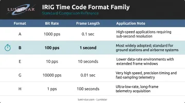
Within the IRIG family, "B" is one of several formats:
| Format | Bit Rate | Frame Length | |--------|----------|--------------|\n| A | 1,000 pps | 0.1 second | | B | 100 pps | 1 second | | E | 10 pps | 10 seconds | | G | 10,000 pps | 0.01 second | | H | 1 pps | 1 minute |
IRIG-B's 100 pulses-per-second rate and 1-second frame length strike a practical balance: enough update frequency for most synchronization needs, yet feasible to transmit over cabling across large facilities and test ranges. The result is that IRIG-B is found in more defense, aerospace, and industrial systems than any other format in the IRIG family — a dominance it has held for decades.
How IRIG-B Timecode Works
Signal Types: Modulated vs. Unmodulated
IRIG-B comes in two fundamental signal forms, each suited to different environments.
Unmodulated IRIG-B (also called DC Level Shift, or DCLS) transmits the time code as a pulse-width coded signal using direct DC voltage transitions with no carrier wave. Key characteristics:
- Compatible with digital logic systems
- Routinely achieves timing accuracy better than 1 microsecond at the receiver (per vendor engineering guidance)
- More susceptible to signal degradation over longer cable runs
- Typically distributed as a 5V TTL signal over 50Ω coaxial cable or shielded twisted-pair
Modulated IRIG-B amplitude-modulates the time code onto a 1 kHz sine wave carrier. As specified in RCC IRIG Standard 200-16, the standard mark-to-space amplitude ratio is 10:3. Practical implications:
- Travels longer distances and tolerates band-limited links better than DCLS
- Historically used for recording on magnetic tape and analog transmission
- Decoding accuracy is lower than unmodulated due to carrier and demodulation effects, typically ranging from tens of microseconds to around 1 ms depending on the decoder
Frame Structure and Data Encoding
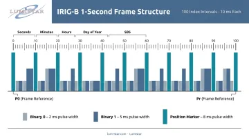
Signal type determines how IRIG-B travels — frame structure determines what it carries. Each frame lasts exactly one second and contains 100 bits transmitted at 100 pulses per second. Bits are encoded using pulse-width modulation within a 10 ms index interval:
- Binary 0 = pulse width of 0.2 × index interval (2 ms)
- Binary 1 = pulse width of 0.5 × index interval (5 ms)
- Position marker = pulse width of 0.8 × index interval (8 ms)
Every frame encodes the following data fields:
- Always present: BCD seconds, minutes, hours, and day of year
- Optional fields: BCD year (00–99), control functions (user-defined), and Straight Binary Seconds (SBS) — a 17-bit count representing seconds since midnight (0 to 86,399)
- No parity or checksum: error detection relies on verifying sequential timestamps across consecutive frames
Position identifier markers occur every 10th bit. Two consecutive markers (P0 frame reference, then Pr) signal the start of a new frame, allowing receiving devices to lock onto the time stream unambiguously.
IRIG-B Format Variants and the Naming Convention
Each IRIG code carries a letter plus three digits. The letter identifies the code family (B = 100 pps, 1-second frame). The three digits encode specific signal attributes, so an engineer can read the format name and immediately know what they're working with.
Decoding the Three-Digit Suffix
| Digit | What It Encodes | Key Values |
|---|---|---|
| First | Modulation type | 0 = DCLS/unmodulated; 1 = sine-wave AM; 2 = Manchester |
| Second | Carrier frequency | 0 = no carrier; 2 = 1 kHz; 3 = 10 kHz; 4 = 100 kHz |
| Third | Data content | 0 = BCD TOY + CF + SBS; 1 = BCD TOY + CF; 2 = BCD TOY only; 3 = BCD TOY + SBS; 4–7 add BCD year variants |
Practical Examples
B122 — sine-wave AM (1), 1 kHz carrier (2), BCD time-of-year only (2). This is a modulated format, common in analog signal distribution and legacy recording setups.
B003 — DCLS/unmodulated (0), no carrier (0), BCD time-of-year + SBS (3). A common unmodulated choice in digital instrumentation systems needing both BCD and straight binary time output.
B000 — DCLS/unmodulated (0), no carrier (0), BCD time-of-year + control functions + SBS (0). SEL and IEEE C37.118 extend this variant for synchrophasor relay applications, where control bits carry additional system state information.
In practice, deployed systems most commonly use B00x variants (unmodulated/DCLS families) and B12x variants (AM/1 kHz families). If a program interface control document specifies a precise variant, use that. Otherwise, confirm the exact format code with the equipment supplier before integration.
IRIG-B Applications: Industries and Use Cases
Aerospace and Flight Test
IRIG-B is the standard timing backbone in flight test operations. Every element of the instrumentation chain must share a common time reference to correlate data streams across multiple sensors and platforms:
- Onboard data acquisition systems
- RF telemetry receivers and ground station processors
- Radar trackers and recording equipment
Even a few microseconds of timing skew can corrupt analysis of high-speed flight dynamics.
Lumistar has supplied IRIG 106-compliant telemetry systems to the aeronautical flight test community since 2000 and builds IRIG-B timing directly into products across its entire line:
- LS-28-DRSM series — accepts IRIG A, B, or G input/output (selectable AC or DC coupled); time-stamps Ethernet UDP data packets in IRIG-218 or Chapter 10 formats, carrying precise temporal information from RF reception through data archiving
- LS-68, LS-18, and LS-50 series — include integrated IRIG time code reader/generator capability with a specified reader latency of 2 microseconds maximum
A concrete example: when Virgin Orbit's LauncherOne Launch Demo 2 mission flew in January 2021, Lumistar's LS-28-DRSM systems captured real-time telemetry throughout the entire flight, providing time-stamped data for both real-time monitoring and post-mission analysis.
Defense Test Ranges and Power Systems
At military test ranges — the very environments IRIG-B was created for — the standard provides synchronized timing across distributed instrumentation spanning large geographic areas. Range Commanders Council member ranges, including White Sands Missile Range, maintain UTC time referenced to the USNO Master Clock, with IRIG-B as the distribution mechanism to range instrumentation.
In the power industry, IEEE 1344-1995 (the IEEE Standard for Synchrophasors for Power Systems) identifies IRIG-B as the basic time communication format for phasor measurements in substation systems, with GPS as the recommended upstream reference. Protective relays, fault recorders, and SCADA systems rely on IRIG-B for sequence-of-events recording, where microsecond-accurate timestamps determine fault causation during grid disturbances.
IRIG-B vs. NTP: Key Differences for Critical Systems
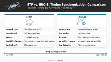
IRIG-B and NTP solve the same problem — distributing time to multiple systems — but through fundamentally different architectures, which determines where each belongs.
NTP distributes time over shared data networks using software-based synchronization. NIST research on practical NTP limitations found that WAN delay asymmetry typically limits NTP time-transfer uncertainty to about 1 millisecond, while even controlled LAN environments achieved roughly 10–20 microseconds under ideal conditions. Network congestion, routing changes, and hardware asymmetry all contribute to variability.
IRIG-B distributes time over dedicated physical wiring using a hardware signal. It's immune to network congestion, routing failures, IP reconfiguration, and denial-of-service conditions. Unmodulated IRIG-B receivers are commonly specified at better than 1 microsecond accuracy — three orders of magnitude better than typical WAN NTP.
When to Use Each
| Scenario | Use NTP | Use IRIG-B |
|---|---|---|
| Server farms, general IT infrastructure | ✓ | |
| Applications where millisecond accuracy is sufficient | ✓ | |
| Flight test data correlation | ✓ | |
| Power fault sequence-of-events recording | ✓ | |
| Radar synchronization | ✓ | |
| High-EMI environments requiring physical isolation | ✓ | |
| Regulatory mandate (IRIG 106, IEEE C37.118) | ✓ | |
| Systems requiring timing independent of data network | ✓ |
The deciding factor isn't precision alone — it's whether your timing infrastructure can tolerate shared-network variability. For flight test data correlation, fault recording, or any application where a few microseconds of ambiguity invalidates results, IRIG-B's hardware-based isolation removes a failure mode that NTP simply can't eliminate by design.
IRIG-B Transmission: Signal Distribution and Cabling
There is no single proprietary "IRIG-B cable." The correct cable depends entirely on the signal format and electrical interface.
Unmodulated IRIG-B distribution options:
- Coaxial cable (e.g., RG-58) at 50Ω — standard for TTL-level single-ended IRIG-B; proper termination is critical for sub-microsecond performance
- Shielded twisted-pair with RS-422 differential signaling — better noise immunity and longer practical distances than single-ended TTL; the preferred choice in modern flight test and industrial environments
- RS-232 is an option only for very short runs
Modulated IRIG-B distribution options:
- Coaxial cable or shielded twisted-pair into high-impedance decoders with automatic gain control
- The signal behaves like audio-frequency analog — AM decoders tolerate impedance variation better than digital logic
Fiber optic distribution is valuable where severe electromagnetic interference is present — near high-power transmitters, jet engines, or power switching equipment. The tradeoff: propagation delay requires measurement and compensation in applications demanding the highest accuracy.
When specifying cabling, document each of the following to avoid integration problems:
- Format variant (B00x or B12x)
- Signal level or AM amplitude
- Termination impedance
- Connector type
- Cable run distance
Vague "IRIG-B cable" procurement language is one of the more common sources of integration failures in time-distribution systems.
Frequently Asked Questions
What is IRIG-B used for?
IRIG-B distributes precise time synchronization across instruments in flight test, defense test ranges, electrical substations, and industrial control systems — covering any application where sub-millisecond or microsecond-level time stamping across multiple devices is required. It is the standard timing backbone for correlating data from different sensors with high temporal precision.
How does IRIG timing work?
IRIG-B encodes time (seconds, minutes, hours, day of year) as pulse-width coded bits transmitted at 100 pulses per second, forming a 1-second data frame. Receiving devices measure the pulse widths to extract the encoded time value and synchronize their internal clocks to the incoming signal, locking to the frame start markers.
How accurate is IRIG-B?
Unmodulated IRIG-B receivers are commonly specified at better than 1 microsecond accuracy relative to the reference source, based on vendor engineering guidance. Modulated IRIG-B is less accurate due to carrier and demodulation effects, typically ranging from tens of microseconds to around 1 ms depending on the decoder design and signal path.
What is the difference between NTP and IRIG-B?
NTP distributes time over data networks and typically achieves millisecond-level accuracy over WANs. IRIG-B uses dedicated physical wiring to deliver microsecond-level accuracy independent of network conditions. For mission-critical applications where timing must be deterministic and network-independent, IRIG-B is the correct choice.
What is the timing source of IRIG-B?
IRIG-B signals come from a time code generator synchronized to a primary reference — most commonly GPS or GNSS, which provides UTC-traceable time. DoD test ranges reference the USNO Master Clock. GPS-disciplined oscillators can achieve frequency stability of approximately 1×10⁻¹³ after one day of averaging, making them the preferred upstream reference for precision timing.
What is an IRIG-B cable?
There is no single standard IRIG-B cable. Unmodulated IRIG-B typically uses 50Ω coaxial cable for TTL single-ended signals, or shielded twisted-pair for RS-422 differential distribution. Modulated IRIG-B uses coaxial or twisted-pair depending on termination requirements. Always specify the signal format, electrical interface, and run distance when selecting cable.