Key Takeaways
- Real-time DAQ captures, digitizes, and delivers sensor data within a defined latency window — enabling live decisions, not just post-flight reviews.
- A complete system spans four layers: sensors/transducers, signal conditioning, ADC hardware, and software/display.
- Four acquisition methods exist: direct wired, RF telemetry, networked (Ethernet/EtherCAT), and wireless — each suited to different environments.
- Flight test telemetry is governed by IRIG Standard 106-24R1, covering PCM framing, RF bands, and data quality requirements.
- Best practices center on Nyquist-compliant sampling, synchronized timing across channels, and continuous data quality monitoring.
What Is Real-Time Data Acquisition?
Picture a test pilot pushing a new aircraft through a high-angle-of-attack maneuver while a ground team watches structural load data stream in live. If that data arrives 30 seconds late, it's useless for the decision being made right now. Real-time data acquisition exists precisely to close that gap.
Real-time DAQ is the continuous process of sampling physical signals from sensors, converting them to digital values, and delivering those values within a latency window short enough to support immediate monitoring or control decisions. Unlike batch data logging, data is actionable during the test — not only after it.
What "Real-Time" Actually Means
"Real-time" doesn't universally mean instantaneous. It means data is delivered within a deterministic, defined time window required by the application. Missing that window is what matters — and that's where the hard/soft distinction becomes practically important.
- Hard real-time: Missing a deadline causes system failure. Flight control actuation is the canonical example — a missed update at the wrong moment has direct physical consequences.
- Soft real-time: Occasional late delivery degrades performance or utility but doesn't cause catastrophic failure. A trend monitoring dashboard falls here. A delayed screen refresh is annoying; it's not dangerous.
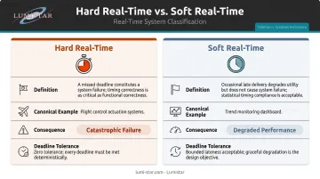
IEEE research on weakly hard real-time systems confirms this framing: hard real-time systems assume no missed deadlines, while soft or firm systems can miss deadlines with bounded consequences. Understanding which category your application falls into determines your entire DAQ architecture.
That architectural choice starts with understanding what a DAQ system actually contains — and where ADCs fit within it.
DAQ vs. ADC: A Common Confusion
An ADC (analog-to-digital converter) is a single component inside a DAQ system — it converts analog voltage to a digital number. A DAQ system is the complete signal chain:
- Sensor input
- Signal conditioning
- ADC conversion
- Transmission and communication
- Software display and recording
Conflating the two leads engineers to over-specify one component while under-specifying the rest of the chain.
Key Components of a Real-Time DAQ System
Sensors and Transducers
Sensors convert physical phenomena into electrical signals the rest of the system can process. In aerospace and industrial DAQ, common types include:
- Strain gauges (structural loads)
- Pressure transducers (aerodynamic and hydraulic systems)
- Accelerometers (vibration, g-loading)
- Thermocouples and RTDs (temperature)
- Voltage and current sensors (avionics health)
A slow-response sensor creates a bottleneck regardless of how fast the downstream hardware is. Sensor selection sets the ceiling on real-time performance before a single wire is run.
Signal Conditioning
Raw sensor outputs are rarely suitable for direct digitization. Signal conditioning prepares them through:
- Amplification of weak signals (strain gauges can output millivolts)
- Anti-aliasing filters to remove frequency components above the Nyquist limit before the ADC sees them
- Bridge completion for resistive sensors
- Isolation for safety-critical or high-voltage environments
- Excitation for active sensors that require a drive voltage
Skipping or under-specifying signal conditioning is one of the most common causes of noisy, misleading real-time data — and the problem often isn't discovered until post-flight analysis.
Analog-to-Digital Conversion (ADC) Hardware
The ADC samples the conditioned analog signal at a defined rate and converts each sample to a digital value. Four metrics determine whether an ADC is right for a given application:
| Metric | What It Controls | Design Rule |
|---|---|---|
| Sampling rate | Temporal resolution | Must be ≥ 2× the highest signal frequency (Nyquist) |
| Bit depth (resolution) | Amplitude granularity | Higher bits = smaller detectable signal changes |
| Dynamic range | Signal spread capability | Must cover both smallest and largest expected values |
| Channel count | Parallel measurement capacity | All channels need timing synchronization to be meaningful |
NI's Nyquist sampling guidance is direct: undersample and you get aliasing — false lower-frequency components that look real but aren't. Higher sample rates improve signal fidelity but increase data throughput demands on every downstream component.
DAQ Software and Display Layer
Software is where raw hardware data becomes actionable information. A real-time DAQ software layer handles:
- Live data streaming and visualization
- Timestamping for post-flight correlation
- Threshold alarming for safety limit monitoring
- Simultaneous archiving while displaying
Common platforms include LabVIEW, MATLAB, Python-based tools, and dedicated vendor applications. Processing overhead in the software layer introduces latency, which is easy to overlook when selecting a platform for high-speed telemetry. For aerospace telemetry specifically, this overhead matters: Lumistar's LDPS (Lumistar Data Processing Software) is designed for flight test applications and integrates directly with their hardware systems, handling real-time display and archiving without the latency introduced by a general-purpose OS.
The 4 Methods of Real-Time Data Acquisition
Direct Wired (Analog and Digital)
The simplest approach: sensors connect via cables directly to DAQ hardware. It delivers the best performance on paper:
- Lowest latency of any acquisition method
- Highest signal integrity with no RF path loss
- Straightforward timing synchronization
The tradeoff is physical. Wired connections become impractical when the system under test is moving, or when cable runs would be prohibitively long or heavy. A static structural test bench is a natural fit. An aircraft at 30,000 feet is not.
Telemetry and RF Transmission
When a physical cable connection is impossible — aircraft in flight, missiles, rockets — telemetry takes over. Sensor data is encoded, modulated onto an RF carrier, transmitted from the vehicle to a ground receiving station, then demodulated and processed for real-time display.
This is the foundational method for flight test DAQ. It's governed in the aerospace domain by IRIG Standard 106-24R1 (published January 2025 by the RCC Telemetry Group), which defines PCM framing, RF frequency band assignments, receiver performance requirements, and data quality metrics.
Key technical challenges unique to this method:
- RF link margin varies continuously as range and aspect angle change during flight
- Doppler effects sweep spectral content during high-speed maneuvers
- Bit synchronization must be maintained to reconstruct the PCM data stream
- Data quality must be actively monitored — IRIG 106-24R1 defines a Data Quality Metric (DQM) that maps estimated bit error probability into a 16-bit word for continuous monitoring
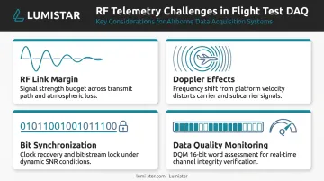
Hardware quality and system design are not optional in this environment. An underspecified receiver fails precisely when the flight profile pushes link margin to its limit.
Networked Acquisition (Ethernet and Industrial Protocols)
Standard Ethernet is not deterministic — packets can be delayed by congestion in ways that are unpredictable. For real-time acquisition on test benches and in factory automation, deterministic industrial protocols fill the gap:
- EtherCAT: Targeted cycle times of ≤100 µs with jitter ≤1 µs, per the EtherCAT Technology Group
- IEEE 802.1 TSN: Provides guaranteed packet transport with bounded latency over standard Ethernet infrastructure
These protocols suit stationary structural test setups and lab bench configurations well. They don't replace IRIG 106 RF telemetry for range interoperability — they solve a different part of the acquisition problem. Where they fall short is mobility: once the test asset leaves the bench, a different acquisition method takes over.
Wireless and IoT-Based Acquisition
Wi-Fi, Bluetooth, and LPWAN-based DAQ systems serve lower-bandwidth, non-safety-critical applications well — environmental monitoring, condition monitoring of rotating machinery, facility instrumentation.
The distinction from telemetry matters for anyone scoping a flight test system. Commercial wireless protocols offer shorter ranges, higher latency variability, and no equivalent to the determinism and interoperability guarantees that IRIG 106 provides. Choosing wireless for a safety-critical flight test application because it's "easier to set up" is a system design risk, not a shortcut.
Real-Time DAQ in Flight Test and Aerospace
Flight test is among the most demanding real-time DAQ environments that exists. The system under test is airborne, moving fast, and cannot be physically connected to recording equipment. Ground engineers must receive live telemetry — from sensors measuring structural loads, temperatures, pressures, vibration, and avionics parameters — in real time to make go/no-go safety decisions as the test unfolds.
The Role of IRIG 106
IRIG 106-24R1 is the compliance baseline for aeronautical telemetry at Range Commander's Council member ranges. It governs:
- PCM framing (Chapter 4): Pulse Code Modulation standards for data formatting
- RF transmitter and receiver systems (Chapter 2): Modulation, frequency band assignments, receiver performance
- Frequency bands: Lower L-band (1435–1525 MHz), Lower S-band (2200–2290 MHz), Upper S-band (2360–2395 MHz)
- Receiver performance: Frequency tolerance within ±0.001%, rejection of undesired frequencies ≥60 dB
- Bit synchronization: Maximum 64-bit intervals between transitions, with randomization required to prevent degenerative PCM patterns
Compliance with IRIG 106 ensures a ground station built by one manufacturer can correctly receive and process data from any IRIG 106-compliant airborne transmitter — essential for federal range programs where interoperability across contractors and test events is mandatory.
Lumistar's Ground Station Approach
Lumistar has focused exclusively on aeronautical flight test telemetry since its founding in 2000. That specialization produced one of the industry's more significant size reductions on record: a typical flight test ground station from less than two decades ago stood 8 feet tall, weighed 250 kg, and consumed several thousand watts. The LS-28-DRSM series reduced that footprint to a unit measuring 6" × 4" × 1.67", weighing under 1 kg, and drawing approximately 45–50 watts — without sacrificing IRIG 106 compliance or real-time performance.
The LS-28-DRSM delivers the complete RF-to-Ethernet signal chain in a single unit. Core capabilities include:
- Dual-channel reception across up to six bands (200 MHz to 7 GHz)
- Diversity combining and demodulation of SOQPSK and Multi-H CPM formats at up to 60 Mbps
- Bit synchronization, frame synchronization, and UDP data streaming
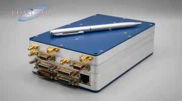
For programs requiring deeper baseband processing, the LS-68-M Digital Processing Engine adds frame sync/decommutation, real-time display, BER monitoring, IRIG time code generation, and data recording. It's available in portable lunchbox, modular, or 1U rack configurations.
The portable LS-28-DRSM-P1 variant packages this capability in an IP-67 rated enclosure with up to 10 hours of battery operation, purpose-built for mobile range operations and antenna pedestal integration.
Best Practices for Real-Time Data Acquisition
Match Sample Rate to Signal Content
The Nyquist rule is a hard engineering constraint. Sample below twice the highest frequency component and the result is aliasing: false low-frequency artifacts that are indistinguishable from real data.
In flight test, different parameters have different bandwidth requirements. A slowly varying airframe temperature needs tens of samples per second. A high-frequency vibration measurement may need tens of thousands. Well-designed DAQ systems support multiple simultaneous sample rates, letting engineers allocate bandwidth where the signal content actually demands it rather than oversampling everything or undersampling the channels that need it.
Prioritize Timing Synchronization
In multi-channel DAQ, all channels must reference a common clock. Without it, correlating a structural load reading with a simultaneous control surface deflection is impossible — the timestamps don't mean the same thing.
Standard synchronization approaches in aerospace DAQ include:
- IRIG time codes (formats A, B, or G per IRIG 200-16, published August 2016) for range-compatible time correlation
- GPS-referenced timing via IEEE 1588 Precision Time Protocol (PTP) for distributed network synchronization
Lumistar's products support both — IRIG A/B/G input/output across the LS-28-DRSM, LS-68-M, and LS-50 decommutator series, with optional PTP IEEE 1588 on multiple platforms. The LS-50-D decommutator's IRIG time reader achieves latency of 2 µs maximum.
Monitor Data Quality Continuously, Not Just Post-Test
A telemetry link that looks fine at takeoff may degrade significantly once the aircraft reaches the edge of the antenna's coverage arc. Waiting until post-flight to discover a 20-minute dropout wastes a test sortie and may leave safety-critical data gaps undetected during the flight.
Real-time quality monitoring means tracking:
- Bit error rate (IRIG 106-24R1's DQM provides a standardized 16-bit quality word)
- Frame synchronization status (loss of frame sync means decommutated parameter values are garbage)
- Sensor out-of-range flags and dropout detection
- RF link margin indicators from the receiver's AGC output
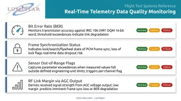
Early detection gives the test team options while the aircraft is still airborne: redirect antenna pointing, adjust transmitter power, or abort a test condition before limits are exceeded. Waiting until landing removes all of those options.
Frequently Asked Questions
What is real-time data acquisition?
Real-time DAQ is the continuous process of sampling sensor signals, converting them to digital values, and delivering that data within a latency window short enough to support live monitoring or immediate control decisions. It differs from batch logging in that data is actionable during the test or process, not only during post-collection review.
What is considered real-time data?
Real-time data is data delivered within a deterministic time constraint defined by the application. The key criterion is whether data reflects the current system state within a window that's actionable for the intended purpose — whether that's a control loop update or a safety monitoring alert.
What are the 4 methods of data acquisition?
The four primary methods are:
- Direct wired — lowest latency, best for stationary systems
- RF telemetry — required for airborne and remote vehicles
- Networked acquisition — Ethernet or deterministic industrial protocols for test benches and factory automation
- Wireless/IoT-based — lower-bandwidth, non-safety-critical monitoring
What is an example of a DAQ system?
A flight test ground station is a complete real-time DAQ system: airborne sensors transmit PCM-encoded data via RF link, a ground receiver demodulates the signal, bit and frame synchronizers reconstruct the data stream, and software displays and archives hundreds of parameters simultaneously. Lumistar's LS-28-DRSM integrates this entire chain into a portable unit under 1 kg.
What software is used for data acquisition?
General-purpose platforms (LabVIEW, MATLAB, Python) and purpose-built vendor applications both serve DAQ needs. For real-time work specifically, the critical requirements are low processing latency, reliable data streaming, live visualization, and simultaneous timestamped archiving.
Is a DAQ system the same as an ADC?
No. An ADC is one component within a DAQ system — specifically the part that converts analog signals to digital values. A full DAQ system encompasses the entire signal chain: sensors, signal conditioning, ADC hardware, transmission or communication, and software for display and recording.