Introduction
Every telemetry signal chain starts at the antenna. If it fails to capture the RF signal, no downstream component — receiver, bit synchronizer, or PCM processor — can recover what was never received. Get that first step wrong and nothing else matters.
For engineers working in aeronautical flight test, this isn't an abstract concern. The FAA's Report to Congress on Aeronautical Mobile Telemetry states directly that loss of AMT data puts the safety of the pilot, aircraft, and people on the ground at risk — and that AMT data loss drives reduced safety, higher cost, and schedule delays across the test program.
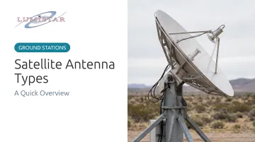
This overview covers the four primary antenna types used in telemetry and satellite communications: parabolic dish, Cassegrain, phased array, and helical. It covers what distinguishes each type and which suits your application.
Key Takeaways
- Satellite antennas focus and deliver RF signals between ground systems and satellites or airborne platforms ; antenna type determines gain, coverage, and tracking capability
- The four main types are parabolic dish, Cassegrain, phased array, and helical , each optimized for a different mission profile
- Parabolic and Cassegrain antennas suit fixed or steerable high-gain applications; phased arrays handle fast, dynamic tracking electronically
- Helical antennas provide circular polarization, making them the right fit for rotating or tumbling platforms
- Matching antenna type to mission requirements prevents signal dropouts, tracking failures, and unnecessary cost
What Is a Satellite Antenna?
A satellite antenna is a device designed to focus, transmit, and receive radio frequency signals between a ground station (or airborne platform) and a satellite or remote RF source. What separates it from a general-purpose antenna is high directivity, precision pointing, and frequency-specific design: these antennas concentrate energy in a narrow beam rather than radiating or receiving omnidirectionally.
Two operational modes apply:
- Downlink — receiving signals from a satellite or airborne transmitter
- Uplink — transmitting signals to a satellite or relay platform
Aeronautical telemetry ground stations primarily operate in receive mode, capturing data transmitted from a test vehicle in flight. Per NASA's smallsat communications guidance, uplink carries commands from Earth and downlink carries data back — each direction has distinct gain, power, and link-margin requirements.
The antenna does not process or decode signals. It focuses and delivers RF energy to the receiver and signal processing equipment downstream. That means antenna performance directly caps everything else in the chain. A receiver with a 3 dB noise figure cannot recover signal that a mismatched or under-gain antenna failed to capture in the first place.
Why Antenna Selection Matters in Aeronautical Flight Test
In flight test, a data dropout is rarely recoverable. The test vehicle has already flown. The maneuver is over. If the antenna lost track or delivered insufficient signal during a critical phase, that data is gone — and the program either accepts a gap in the safety record or plans another sortie.
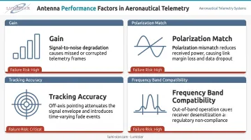
The antenna variables that determine whether signal reaches the receiver are:
- Gain — determines how effectively the antenna concentrates received energy, directly setting the signal-to-noise ratio at the receiver
- Polarization match — a mismatch between antenna polarization and the transmitter's radiated polarization causes signal loss that no downstream component can recover
- Tracking accuracy — for a moving test vehicle, the antenna must follow the target; pointing error reduces received gain, and sufficient pointing error drops the signal entirely
- Frequency band compatibility — the antenna must be designed for the band the test vehicle is transmitting on
Ground telemetry systems — including the RF receivers, demodulators, bit synchronizers, and PCM processing equipment they incorporate — can only perform as well as the antenna feeding them. Lumistar's telemetry ground station receivers, for example, support frequency bands from 200 MHz to 6 GHz covering L-band, S-band, and C-band allocations aligned with IRIG 106-20 standards. An antenna operating outside that band, or delivering marginal signal, negates the receiver's capability entirely.
Antenna type selection is an engineering decision made at the program level, not something resolved during procurement.
Types of Satellite Antennas
No single antenna type is universally correct. Each design trades gain, bandwidth, beamwidth, polarization, mobility, and complexity differently. Mission requirements determine which trade-off is acceptable.
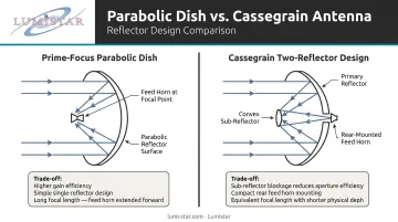
Parabolic Dish Antenna
A parabolic dish uses a curved (paraboloid) reflective surface to focus incoming RF signals onto a feed horn at the focal point. The feed delivers the concentrated signal to a low-noise amplifier and receiver. Two common variants exist: the prime-focus design places the feed directly in front of the dish; the offset variant positions it to the side, eliminating feed blockage and improving aperture efficiency.
Best suited for: Fixed or motorized ground station installations tracking geostationary satellites or slower-moving airborne test vehicles. Widely used in telemetry ground stations, VSAT, and earth station applications where the target is predictable and high gain is the priority.
Key characteristics:
- High gain relative to aperture size
- Mechanically steered — the entire dish rotates to track a moving target
- Cost-effective and straightforward to manufacture
- Well-documented for telemetry applications; DTIC sources document a 5-meter parabolic reflector used as an S-band receive antenna in missile telemetry ground stations
Limitations:
- Requires continuous physical repositioning to track fast-moving targets
- Susceptible to wind loading and mechanical wear on tracking drives
- Bulky form factor limits deployability
Cassegrain Antenna
A Cassegrain antenna uses two reflectors: a large concave primary and a smaller convex sub-reflector positioned near the primary's focal point. The signal reflects from the sub-reflector back through an aperture in the primary to a feed horn mounted at the rear of the dish.
This geometry produces a longer effective focal length without increasing physical dish size — a meaningful advantage when integrating complex feed electronics in constrained installations.
Best suited for: Large, high-performance ground station applications requiring precision reception at long range. Common in deep space communication, professional satellite uplink/downlink earth stations, and radar systems. JPL's Deep Space Network uses large dual-reflector antenna systems extensively.
Key characteristics:
- Rear-mounted feed simplifies waveguide and electronics integration
- Compact feed assembly relative to focal length
- Preferred when feed integration and long focal length matter
Important caveat: The gain and sidelobe advantages of Cassegrain designs are geometry-dependent, not universal. An IEEE study found that sub-reflector blockage in a 24-wavelength Cassegrain case produced 2.3 dB lower gain and 5.7 dB higher sidelobe levels — so sub-reflector sizing and placement require careful modeling before committing to a design. JPL analysis also documents Ka-band gain loss on large DSN antennas due to gravity-induced deformation with elevation angle.
Limitations:
- More mechanically complex and expensive than a standard parabolic dish
- Sub-reflector alignment is sensitive to thermal deformation
- Not practical for portable or rapidly deployable configurations
Phased Array Antenna
A phased array consists of hundreds to thousands of small radiating elements arranged in a flat or curved panel. By electronically adjusting the phase of the signal fed to each element, the array steers its beam in any direction within its field of view — with no physical movement of the antenna structure.
Best suited for: Tracking high-speed airborne test vehicles, UAVs, missiles, and LEO satellites where mechanical tracking cannot keep pace with target motion. NASA NTRS research documents a K-band phased array for LEO communications capable of 622 Mbps per beam, demonstrating the data throughput achievable with electronic beam steering.
Key characteristics:
- Beam steering occurs in microseconds, unconstrained by any mechanical slew rate
- Can track multiple targets simultaneously with independent beams
- Adaptable beam shape for changing signal environments
- No moving parts subject to mechanical wear
Lumistar's defense and flight test customers often run test programs — high-performance aircraft, maneuvering UAVs, hypersonic vehicles — where phased array integration is the only practical tracking solution.
Limitations:
- Substantially higher cost and complexity than reflector-based antennas
- Requires sophisticated beamforming electronics and calibration
- Element failures can degrade performance without obvious external signs
- Gain per unit area is lower than a large parabolic dish of equivalent aperture

Helical Antenna
A helical antenna consists of a conductive element wound in a helix above a ground plane. In axial mode — the primary configuration for satellite and telemetry use — the helix produces a circularly polarized beam along its axis. The signal's electric field rotates as it propagates rather than oscillating in a fixed plane.
Best suited for: Airborne installations on test vehicles where platform attitude changes frequently, and ground station applications where polarization stability across varying geometries is required. NASA NTRS documents a ground-based right-circularly-polarized tri-helix telemetry antenna array operating in the 225–250 MHz range, and NASA's self-deployable helical antenna program produced prototypes in S-band, X-band, and Ka-band.
Where it fits best in practice:
- Native circular polarization resists polarization mismatch when the transmitting platform rotates or tumbles — particularly valuable on spinning or maneuvering test vehicles
- Wide beamwidth relative to physical size covers a larger portion of sky without steering
- Relevant for airborne transmitters, weather satellites, and LEO applications
Limitations:
- Lower gain than a parabolic dish of comparable aperture size
- Physically larger than patch or microstrip antennas
- Performance is sensitive to helix geometry tolerances — small errors in pitch or diameter affect polarization purity and gain
How to Choose the Right Antenna for Your Application
Start with the mission requirement, not the antenna catalog. The correct type is determined by what the program actually needs.
Step 1: Define the Primary Performance Driver
Ask which of these matters most for your application:
- Maximum gain at a fixed or slowly changing pointing angle
- Beam agility for dynamic tracking of fast or maneuvering targets
- Circular polarization stability across varying platform attitudes
- Compact or lightweight form factor for mobile or airborne installation
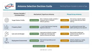
Step 2: Evaluate These Four Variables
| Variable | Guidance |
|---|---|
| Target motion profile | Geostationary or slow-moving targets → parabolic or Cassegrain; fast jets, missiles, LEO satellites → phased array |
| Frequency band | Higher frequencies (Ku, Ka) demand tighter surface tolerances and precise pointing; L, S, C-band are more forgiving |
| Gain and link budget | Calculate required antenna gain from the link budget; confirm the selected type can deliver it within available aperture |
| Deployment environment | Fixed ground station vs. transportable vs. airborne each imposes different size, weight, ruggedization, and wind-load constraints |
Step 3: Account for Total Cost of Ownership
Procurement price is only part of the equation:
- Dish-based systems require mechanical maintenance — tracking drives, pointing calibration, wind-load management
- Phased arrays require electronics calibration and beamforming upkeep
- Confirm all antenna types are compatible with the downstream receiver and signal processing chain — feed polarization, connector interfaces, and frequency band must all match
Step 4: Avoid Default Choices
A large Cassegrain is not the right answer for a portable flight line application, just as a small helical antenna is not appropriate for long-range tracking of a supersonic test vehicle. Verifying antenna feed compatibility against your receiver's published specifications — before procurement — eliminates one of the most common integration failures in the field.
Conclusion
Satellite antennas are the first link in every telemetry and satellite communication chain — and the one that shapes every downstream signal quality metric. Gain, polarization match, tracking accuracy, and frequency band compatibility are all determined at the antenna, before any signal processing occurs.
Understanding the core trade-offs between parabolic dish, Cassegrain, phased array, and helical designs lets engineers and program managers make selection decisions that align with their actual mission profile rather than defaulting to the most familiar option.
That decision, made at the program planning stage, is what prevents data dropouts, tracking failures, and the costly re-flies that follow when antenna performance falls short of mission requirements.
Frequently Asked Questions
What are the different types of satellite antennas?
The four primary types are parabolic dish, Cassegrain, phased array, and helical. Each optimizes differently for gain, polarization, beam agility, and deployment environment. Selection depends on the specific mission profile, platform constraints, and frequency requirements.
What antenna type is widely used in satellite television?
The offset parabolic dish is the dominant type for direct-to-home satellite TV. Its high gain, cost-effectiveness, and feed-blockage-free geometry make it well-suited for fixed residential installations receiving Ku-band broadcast signals from geostationary satellites.
What is the difference between a parabolic and a Cassegrain antenna?
A parabolic dish uses a single reflector with a front-mounted feed horn at the focal point. A Cassegrain adds a convex sub-reflector that redirects the signal to a rear-mounted feed, producing a longer effective focal length in a more compact form factor with cleaner feed integration.
Can phased array antennas track fast-moving airborne vehicles like test aircraft?
Yes — this is one of their primary advantages. Phased array beam steering is electronic, not mechanical, so beam repositioning occurs in microseconds. That eliminates the slew rate limitation of mechanically pointed dishes and enables reliable tracking of high-speed, maneuvering aircraft, UAVs, and missiles.
What frequency bands are typically used in flight test telemetry?
IRIG 106-20 specifies allocations in Lower L-band (approximately 1435–1535 MHz), S-band (2200–2395 MHz), and C-band (4400–5250 MHz). Ku and Ka bands are used for satellite relay applications but demand more precise pointing and are more susceptible to atmospheric attenuation.
How does antenna gain affect telemetry signal quality?
Antenna gain determines how effectively the antenna concentrates received energy onto the receiver's input. Higher gain captures weaker signals from greater distances or through higher path losses, directly improving the signal-to-noise ratio and reducing the risk of data dropouts during critical, non-repeatable flight test phases.