The choice of frequency band, link architecture, and transmitter design directly affects data throughput, link reliability, and IRIG 106 compliance. Get the selection wrong and you're chasing dropped data packets during the most critical test points in the envelope.
This guide covers how satellite transmitters work, which frequency bands apply to aeronautical telemetry and why, the three fundamental link types, the design parameters that drive hardware selection, and the regulatory requirements you need to address before first flight.
TL;DR: Satellite Transmitter Communication Options at a Glance
- A satellite transmitter modulates digital telemetry onto an RF carrier, amplifies it, and radiates it toward a receiving terminal
- S-band (2200–2395 MHz) is the primary aeronautical telemetry band; X-band handles high-rate payload downlinks; L-band and UHF serve long-range relay
- Link direction matters: downlink moves data from vehicle to ground, uplink from ground to vehicle, and crosslink relays between satellites
- Four design levers drive every transmitter selection: link budget, SWaP constraints, modulation choice, and antenna design
- NTIA coordinates federal AMT spectrum; FCC governs non-federal operations; IRIG 106-24 sets the technical standard for waveforms and data formats
What Is a Satellite Transmitter and How Does It Work?
A satellite transmitter is a subsystem that takes digital data — flight test telemetry, health monitoring, sensor streams — modulates it onto an RF carrier wave at a designated frequency, amplifies it, and radiates it through an antenna toward a receiving terminal. On the receive end, a complementary system demodulates the signal to recover the original data.
The Transmit Chain
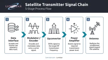
The basic signal path runs through five stages:
- Data interface — ingests raw sensor or telemetry data
- Modulator/encoder — converts data to a modulated RF signal; this stage largely determines link performance
- Upconverter — shifts the signal to the designated transmission frequency
- Power amplifier — boosts signal strength for the link distance
- Antenna — radiates the signal toward the receiving terminal
Coding schemes such as LDPC (Low-Density Parity-Check Code) protect data integrity over long, noisy paths. IRIG Standard 106-24 standardizes LDPC in Appendix 2-D with code rates of 1/2, 2/3, and 4/5 and block sizes of 1,024 or 4,096 bits.
The Receive Chain
On the receive side, a low-noise amplifier (LNA) captures the weak incoming signal, a bandpass filter rejects out-of-band interference, and a demodulator reconstructs the digital bitstream. The RCC Document 120-21 Telemetry Systems RF Handbook describes telemetry systems ranging from a single transmitter and antenna to complex multi-transmitter configurations with directional couplers and coaxial switches.
Transmitter vs. Transponder
These terms are not interchangeable:
- Transmitter: sends data in one direction only — from the test vehicle to the ground
- Transponder: receives on one frequency (uplink) and retransmits on another (downlink), used in relay satellite architectures to extend range beyond line-of-sight
In a typical aeronautical flight test program, a transmitter mounted on the test vehicle sends sensor and health data to a ground receiving station — sometimes through a satellite relay that extends the link beyond line-of-sight range.
Key Satellite Communication Frequency Bands for Aeronautical Telemetry
Higher frequencies support higher data rates but face greater atmospheric attenuation and demand tighter antenna pointing. Lower frequencies offer link robustness and simpler regulatory coordination but carry less bandwidth. Each band occupies a distinct niche — the sections below map those niches against real AMT constraints.
The FAA's Report to Congress on Aeronautical Mobile Telemetry makes one constraint explicit: although aircraft may collect sensor data at gigabit-per-second rates, bandwidth limits typically restrict actual AMT transmission to 5–15 Mbps. Transmitter selection should begin with that bandwidth ceiling.
S-Band: The Aeronautical Telemetry Workhorse
S-band covers the primary U.S. AMT allocations at 2200–2290 MHz and 2360–2395 MHz. It's the dominant band for aeronautical Tracking, Telemetry, and Command (TT&C) because:
- Mature hardware ecosystem with established range infrastructure
- Reasonable atmospheric performance across most operational environments
- Basis of IRIG 106 aeronautical telemetry frequency allocations
- Practical data rates up to approximately 10–15 Mbps in typical configurations
The tradeoff: S-band is congested. NTIA's 2360–2390 MHz compendium notes that NASA missions requiring multiple wideband telemetry links cannot always be accommodated in 2200–2290 MHz due to spectrum congestion. Program planners should coordinate spectrum access early — waiting until integration phase creates scheduling risk.
L-Band and UHF: Long-Range and Relay Options
Where S-band congestion limits options, L-band and UHF fill a different role. L-band's primary AMT allocation runs 1435–1525 MHz per NTIA; both bands offer excellent propagation characteristics suited to long-range and over-the-horizon relay through commercial satellite constellations.
The key limitation: data rates are generally below 1 Mbps, which rules out high-rate sensor streams. L-band and UHF are viable for command/control links and lower-bandwidth telemetry where range matters more than throughput.
X-Band and Ka-Band: High-Rate Downlinks
X-band (8–12 GHz) provides significantly higher data throughput than S-band and is used for high-rate payload data downlinks in defense and aerospace test programs.
Ka-band (27–40 GHz) extends capacity further, but introduces two serious complications:
- Rain fade susceptibility—ITU-R P.618-14 provides Earth-space propagation prediction, and ITU-R P.838-3 models specific rain attenuation; Ka-band links require explicit fade margin analysis, not just a faster modem
- Precise antenna pointing requirements that are difficult to meet on maneuvering airborne platforms
Ka-band works best on fixed ground stations or stabilized airborne platforms — chase aircraft with precision gimbaled antenna systems, for example — where pointing errors stay within fraction-of-a-degree tolerances.
Band Selection Summary
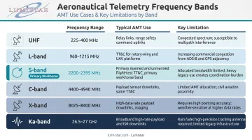
| Band | Frequency | Typical AMT Use | Key Limitation |
|---|---|---|---|
| UHF | 300 MHz–1 GHz | Command/control relay | Low data rate |
| L-band | 1435–1525 MHz | Long-range AMT, relay | Low data rate |
| S-band | 2200–2395 MHz | Primary TT&C, telemetry | Spectrum congestion |
| C-band | 4400–5250 MHz | Higher-rate AMT | Less common, fewer ranges |
| X-band | 8–12 GHz | High-rate payload downlink | Pointing, complexity |
| Ka-band | 27–40 GHz | Wide-bandwidth relay | Rain fade, pointing |
Types of Satellite Transmitter Communication Links
Three fundamental link types define any aeronautical telemetry architecture:
- Downlink: test vehicle or relay satellite transmits to a ground station—this is the primary link in virtually all flight test programs
- Uplink: ground station transmits commands or reference signals to the vehicle—used for command and control, not high-rate data
- Crosslink: inter-satellite relay that extends coverage beyond the line-of-sight of any single ground station
How Satellite Relay Architectures Work
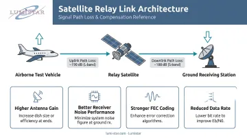
In a relay architecture, an airborne transmitter sends telemetry to a relay satellite, which retransmits the signal to a distant ground station. This extends telemetry range beyond the horizon of any single direct link.
The cost is path loss. RCC Document 120-21 gives free-space path loss as:
Lt = 36.58 + 20 log(D) + 20 log(f)
where D is distance in statute miles and f is frequency in MHz. Loss increases by 6 dB every time distance doubles. Adding a satellite relay hop forces that additional path loss into the link budget. Engineers must compensate using one or more of the following:
- Higher antenna gain
- Better receiver noise performance
- Stronger forward error correction coding
- Reduced data rate
Propagation delay increases with each relay hop—latency that must be explicitly modeled in any real-time command loop analysis.
Critical Design Considerations When Selecting a Transmitter
Starting with the Link Budget
The link budget is the foundational design tool—not transmit power alone. It calculates whether the received signal will have sufficient strength and quality to be decoded reliably. Key parameters:
- EIRP: transmit power adjusted by line losses and antenna gain
- Free-space path loss: function of distance and frequency
- Atmospheric attenuation: molecular absorption, rain fade at higher bands
- Receive antenna gain and noise figure
- Required Eb/N0: determined by modulation and target BER
Every other design decision flows from the link budget. NTIA's 1435–1525 MHz compendium documents assignment power levels from 2 W to 100 W in that band, reflecting the wide range of actual deployment scenarios.
Data Rate vs. Power vs. SWaP
Higher data rates require more RF output power or higher antenna gain to maintain the same link margin. On an airborne platform, that directly conflicts with SWaP constraints.
Capable airborne transmitters typically support S and C-band configurations with RF output up to 18 W, a representative figure for modern flight test platforms. The practical resolution to the data rate/power tension usually involves:
- Selecting bandwidth-efficient modulation (SOQPSK-TG over legacy PCM/FM)
- Adding LDPC coding to buy link margin without more power
- Accepting a lower data rate when the link budget demands it
Modulation and Coding: Where Efficiency Is Won
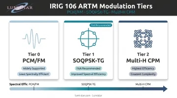
IRIG 106-24 standardizes three primary modulation formats:
- PCM/FM (ARTM Tier 0): legacy format, widely supported, least spectrally efficient
- SOQPSK-TG (ARTM Tier 1): the FAA identifies this as the preferred format for improving spectral efficiency; it fits more data into the same bandwidth
- Multi-H CPM (ARTM Tier 2): highest spectral efficiency, greater complexity
SOQPSK-TG is the standard for new S-band telemetry designs. IRIG 106 compliance in modulation choice matters because it ensures interoperability with government and commercial range receiving infrastructure—a transmitter using a non-standard waveform may not be recoverable at the range ground station.
LDPC coding provides additional link margin without requiring more transmit power. Combined with SOQPSK-TG, it addresses both spectral congestion and link reliability simultaneously.
Antenna Selection for Airborne Platforms
Two primary options, each with a clear use case:
- Omni-directional antennas (patch, blade): simple, tolerant to aircraft attitude changes, no tracking required; preferred for most flight test transmitters where maneuverability means unpredictable orientation
- Directional antennas: higher gain improves link margin and extends range, but require tracking mechanisms that add mass, complexity, and potential failure modes
For most test aircraft and UAVs, omni antennas are the right call. Directional antennas make sense on larger, more stable platforms where the additional gain is necessary to close the link budget.
Regulatory and Licensing Requirements for Aeronautical Telemetry
Regulatory coordination is an early design constraint, not a final paperwork step. It directly affects hardware selection, so it needs to be addressed before components are specified.
For federal operators, aeronautical telemetry transmitters operating on AMT bands are coordinated through the NTIA. IRIG 106-24 specifies the technical requirements: frequency allocations, approved modulation formats, coding, and data formats. Compliance is required for interoperability with Major Range and Test Facility Base (MRTFB) receiving infrastructure.
For non-federal operators, the regulatory path depends on the specific architecture:
- 47 CFR Part 5 (Experimental Radio Service): governs experimental radio operations
- 47 CFR Part 25 (Satellite Communications): applies to space station and Earth station licensing
- Part 87 (Aviation Services) may also apply depending on the operational context
Do not assume which rule applies—verify with FCC counsel before hardware selection.
Range Scheduling
Securing the appropriate license is only part of the regulatory picture. Range scheduling requires separate coordination with the specific test range—Eglin's 96 TW/XPO Range Operations, NAVAIR's Atlantic Ranges and Targets, and others—and must be built into program planning timelines well before first flight. Frequency conflicts identified late have pushed test program schedules by weeks or months.
How Ground Station Receiving Systems Complete the Telemetry Link
The transmitter is only half the communication link. A capable ground receiving station must track the airborne transmitter, capture the signal, demodulate it, and deliver processed data to the analyst—the ground system's quality directly determines how much of the transmitted data is successfully recovered, particularly at the edge of the flight envelope.
Key ground station functions that interface with the telemetry link:
- Tracking antennas or omni receive arrays
- LNA front ends (4–5 dB noise figure is typical in quality systems)
- Receivers tuned to the transmitter's frequency band
- Demodulators supporting the transmitter's modulation format
- Bit synchronizers, frame synchronizers, and data recorders
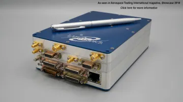
One significant development over the past two decades: ground stations have compressed dramatically. Systems that once occupied 8-foot racks weighing 250 kg and consuming thousands of watts now fit in a hand-held unit under 1 kg and 50 watts. Lumistar's LS-28-DRSM series, introduced in 2017, represents this shift directly.
The IRIG 106-compliant LS-28-DRSM delivers complete ground station functionality in a modular unit measuring 6" × 4" × 1.67" and weighing under 1 kg. Core capabilities include dual-channel RF reception from 200 MHz to 6 GHz, diversity combining, SOQPSK-TG demodulation, bit synchronization, and Ch10 UDP data output.
The system covers S-band (2200–2400 MHz), lower L-band (1435–1540 MHz), C-band, and other AMT allocations at data rates up to 60 Mbps. Its firmware-based architecture allows modulation formats and DSP algorithms to be updated electronically as transmitter requirements evolve, with no hardware replacement required.
Matching ground station configuration to the transmitter's specific frequency band and modulation format is what closes the telemetry link. When those parameters align, data recovery holds even at the margins of the test envelope — where it matters most.
Frequently Asked Questions
What is a satellite transmitter?
A satellite transmitter converts data or signals into modulated RF waves and transmits them wirelessly to a receiving station. In aeronautical telemetry, it sends sensor and vehicle health data from an airborne test platform down to the ground station for processing and display.
What frequency band is best for aeronautical telemetry?
S-band is the most widely used for aeronautical telemetry due to its mature ecosystem and IRIG 106 standardization. X-band is preferred when higher data rates are required; L-band and UHF are used for long-range relay applications where throughput requirements are lower.
What is the difference between a satellite transmitter and a transponder?
A transmitter sends signals in one direction only. A transponder both receives and retransmits—it receives an uplink signal on one frequency and retransmits it as a downlink on another. Transponders are the core of satellite relay architectures.
What does IRIG 106 mean for telemetry transmitters?
Compliance with IRIG 106 is required for interoperability with government test range receiving infrastructure. The standard specifies frequency allocations, approved modulation formats (including SOQPSK-TG), coding schemes (LDPC), and data formats for aeronautical telemetry systems.
How does link budget affect transmitter selection?
The link budget determines whether the received signal will have sufficient strength to be decoded reliably. It drives the required transmit power, antenna gain, and coding rate, directly governing the size, weight, and power (SWaP) tradeoffs that constrain hardware selection on airborne platforms.
What is the difference between uplink and downlink in aeronautical telemetry?
The downlink carries sensor and health data from the aircraft to the ground receiving station. The uplink sends commands or reference signals from the ground to the aircraft. Most telemetry programs are downlink-intensive; uplink is used primarily for command and control.