The stakes are real. Modulation affects spectral efficiency, IRIG 106 compliance, receiver compatibility, and SWaP performance simultaneously. Get it wrong, and you're either redesigning hardware mid-program or applying for a range waiver you'd rather not need.
This guide covers the major modulation schemes used in aeronautical flight test telemetry—PCM/FM, SOQPSK-TG, ARTM CPM, and others—along with a practical decision framework for selecting the right one for your application.
Key Takeaways
- Modulation encodes sensor data onto an RF carrier, controlling bandwidth use, noise immunity, and PA efficiency
- PCM/FM remains widely deployed, but SOQPSK-TG (ARTM Tier I) delivers roughly 2× the spectral efficiency with comparable BER performance
- ARTM CPM (Tier II) pushes to nearly 3× PCM/FM efficiency, but requires significantly more complex ground-side demodulation
- Selection depends on spectrum allocation, data rate, link margin, SWaP constraints, and ground station receiver capability
- Firmware-selectable transmitters (such as Lumistar's LS-18 and LS-19 series) allow modulation changes without hardware redesign
What Is Modulation in Telemetry Transmitters?
Modulation is the process of encoding digital information—sensor readings, vehicle state data, video streams—onto an RF carrier signal for wireless transmission to a ground station. Without modulation, baseband PCM data cannot traverse the kilometers-long link between an airborne test vehicle and a ground receiver.
In flight test telemetry, the data being modulated is typically a serialized PCM bitstream: a Time-Division Multiplexed (TDM) sequence of binary-coded sensor words, as defined in RCC 106-24 Chapter 4. A commutator interleaves multiple sensor channels into this single stream before it reaches the modulator.
Why Constant-Envelope Modulation Dominates
Three fundamental parameters can be varied to carry information: amplitude, frequency, and phase. Modern aeronautical telemetry relies almost exclusively on frequency- and phase-based schemes, not amplitude.
The constraint comes down to the power amplifier. Airborne transmitters use saturated, nonlinear PAs (Class C or Class E) because they are far more power-efficient than linear PAs. These amplifiers distort any signal with amplitude variations, causing spectral regrowth and out-of-band emissions.
Constant-envelope modulations (PCM/FM, SOQPSK-TG, ARTM CPM) maintain fixed amplitude regardless of the data being transmitted, which lets the PA run at full saturation without signal distortion—ideal for battery-powered or power-limited airborne platforms.
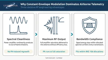
The practical case for constant-envelope schemes comes down to three factors:
- Spectral cleanliness: No amplitude variation means no PA-induced spectral regrowth or out-of-band interference
- Maximum RF output: The PA operates at full saturation, preserving every watt of link budget
- Compliance with bandwidth allocations: Defined in IRIG 106, these modulations fit within the aeronautical telemetry spectrum without coordination issues
As noted in Shaw's 2014 BYU aeronautical telemetry study, linear modulations like APSK require PA backoff to avoid nonlinear distortion, directly reducing transmitted RF power and link distance.
Common Modulation Schemes for Telemetry Transmitters
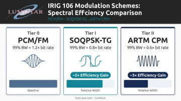
Flight test telemetry modulation has progressed from analog FM-based schemes toward spectrally efficient digital phase modulations, all governed under IRIG 106. The progression maps loosely to ARTM tiers: PCM/FM (Tier 0 legacy baseline), SOQPSK-TG (Tier I), and ARTM CPM (Tier II).
PCM/FM
PCM/FM is the historical workhorse of flight test telemetry—used as the primary aeronautical format for more than 40 years. NRZ-L data frequency-modulates the carrier. Per RCC 106-24 Chapter 2, the recommended modulation index is h = 0.7, with optimum peak deviation equal to 0.35 × bit rate.
99% occupied bandwidth: approximately 1.2 × bit rate (ITC 2003)
PCM/FM remains relevant because:
- Enormous installed base of compatible receivers at U.S. test ranges
- Simple, well-characterized receiver design
- Predictable BER vs. Eb/N0 for link budget calculations
- Adequate for lower data rate applications where spectrum isn't constrained
Its weakness is spectrum. As channel congestion grows, PCM/FM's wide bandwidth footprint becomes a scheduling liability at crowded ranges.
SOQPSK-TG (ARTM Tier I)
SOQPSK-TG is the ARTM Tier I standard under IRIG 106 Chapter 2. It's a constant-envelope, continuous-phase modulation with a constrained ternary alphabet and modulation index of 0.5.
Its frequency pulse uses a spectral raised-cosine shape, which eliminates the abrupt phase transitions that cause spectral splatter in simpler schemes.
99% occupied bandwidth: approximately 0.8 × bit rate (ITC 2003)—a roughly 2× spectral efficiency gain over PCM/FM
Key advantages:
- Comparable BER performance to PCM/FM in AWGN
- Compatible with nonlinear PAs (constant envelope)
- Fits within tighter spectral masks, reducing adjacent-channel interference risk
- Supported by modern SDR-based ground station receivers
For programs where spectrum is increasingly constrained—which describes most U.S. ranges today, given the ever-increasing demand for aeronautical test spectrum documented by AFTRCC in 2024—SOQPSK-TG is the natural upgrade path from PCM/FM.
ARTM CPM (Tier II)
ARTM CPM uses a quaternary symbol alphabet with alternating modulation indices of 4/16 and 5/16, and a three-symbol-long raised cosine frequency pulse. The multi-index, memory-across-symbols architecture delivers the tightest spectral containment of any IRIG-standardized scheme.
99% occupied bandwidth: approximately 0.6 × bit rate (ITC 2003)—nearly 3× the spectral efficiency of PCM/FM
The cost is receiver complexity. The optimal coherent detector requires 128 real matched filters and a Viterbi trellis of 512 states and 2048 branches. That is not a casual firmware update for a legacy ground station.
Practical guidance:
- Reserve Tier II for high-data-rate programs (HD video, dense sensor arrays) where spectrum is the binding constraint
- Confirm ground station demodulator capability before committing to Tier II
- In ITC 2003 flight tests at Edwards, Tier II availability was 73% vs. 82% for Tier I—a real link performance tradeoff to account for in your budget
MSK and Higher-Order Schemes
MSK (Minimum Shift Keying) is a special case of CPFSK where peak deviation equals half the bit rate. It maintains constant envelope, supports nonlinear PA operation, and offers good BER performance—making it compatible with airborne platforms. GMSK adds Gaussian pulse shaping for additional spectral compactness.
In terms of standardization and airborne suitability, these schemes differ significantly:
- MSK / GMSK: Not in current IRIG 106 standardized waveform tables, but present in some legacy and commercial telemetry products; constant envelope supports nonlinear PAs
- M-ary PSK, APSK, QAM: Used in satellite downlinks and some UAV data links, but the linear amplifier requirement makes them poorly suited for airborne telemetry transmitters where PA efficiency is critical
How to Choose the Right Modulation Scheme
Modulation selection is a systems engineering decision, not a waveform specification exercise. It must connect transmitter hardware constraints, range infrastructure, spectrum allocation, and IRIG 106 compliance into a coherent choice.
Spectral Efficiency and Allocated Bandwidth
Aeronautical telemetry operates in specific allocated bands. Per RCC 106-24 Chapter 2, the primary bands are:
| Band | Frequency Range |
|---|---|
| Lower L-band | 1435–1525 MHz |
| Lower S-band | 2200–2290 MHz |
| Upper S-band | 2310–2395 MHz |
| Lower C-band | 4400–4940 MHz |
| Middle C-band | 5091–5150 MHz |
IRIG 106 defines spectral mask compliance using: M(f) = K − 10logR − 100log|(f − fc)/R|, where K = −28 for binary PCM/FM, −61 for SOQPSK-TG, and −73 for ARTM CPM. The tighter K values for Tier I and II reflect their better spectral containment.
As spectrum congestion increases, higher-efficiency modulations directly reduce adjacent-channel interference risk and improve channel reuse across a range.
Data Rate Requirements
The relationship between data rate and bandwidth differs across schemes:
- PCM/FM: bandwidth scales at ~1.2× bit rate—fine for lower-rate programs, but consumes spectrum fast as data rates climb
- SOQPSK-TG: ~0.8× bit rate—when your PCM/FM signal starts bumping against adjacent channel masks, Tier I provides headroom
- ARTM CPM: ~0.6× bit rate—essential when HD video or high-channel-count sensor arrays push data rates above what Tier I can accommodate within your assigned channel
There's no universal Mbps crossover point. The trigger is spectral mask compliance: when PCM/FM at your required data rate can no longer fit within your assigned channel bandwidth, move to SOQPSK-TG. When SOQPSK-TG can't fit, evaluate Tier II—and verify your ground station can handle it.
Link Margin and BER Proven Performance
Bandwidth efficiency and link margin are inseparable decisions. PCM/FM and SOQPSK-TG have well-characterized, similar BER vs. Eb/N0 curves, making link budget calculations straightforward. ARTM CPM achieves BER = 10⁻⁵ at Eb/N0 = 10.75 dB with an optimal coherent detector.
Synchronization thresholds matter for high-dynamic flight test vehicles:
- PCM/FM (RCB2000 bit synchronizer): ~3.5 dB Eb/N0
- SOQPSK-TG (Tier I): ~4 dB Eb/N0
- ARTM CPM (Tier II): ~9 dB Eb/N0
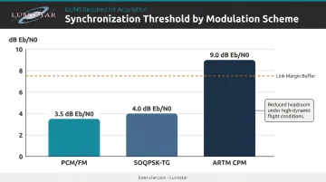
Doppler shift, multipath fading, and two-ray interference (reflected-path delays of 20–500 ns are typical at Edwards) all reduce effective SNR. Higher synchronization thresholds shrink your link margin buffer—for low-elevation or high-speed profiles, ARTM CPM's 9 dB threshold leaves less headroom to absorb those losses.
SWaP Constraints
All three IRIG-standardized schemes are constant-envelope, so all three support saturated PA operation. That narrows the SWaP question to overall transmitter power draw and physical form factor.
Key considerations for power-limited platforms:
- UAVs and sounding rockets often have strict watt-hour budgets where PA efficiency is decisive
- Constant-envelope modulations eliminate the PA backoff penalty entirely
- Transmitter power is capped at 25 W EIRP maximum per RCC 106-24 Chapter 2—the modulation scheme affects how efficiently you use that ceiling
For battery-powered or expendable vehicles, the PA stage and modulator together often determine whether a mission is feasible at a given link distance.
IRIG 106 Compliance and Ground Station Compatibility
IRIG 106 exists for interoperability at RCC member ranges. Eglin AFB operates as an RCC member range; Edwards AFB's 412th Test Wing uses IRIG 106 Chapter 7 packet telemetry on multiple platforms. Non-conforming modulations require explicit justification—RCC 106-24 states that nonconforming systems are "highly discouraged."
Verify receiver compatibility before finalizing your design. Legacy receivers may only support PCM/FM and PM; modern SDR-based or multi-mode receivers handle SOQPSK-TG and ARTM CPM. Discovering a mismatch at integration can require hardware redesign, schedule slips, and range re-coordination—confirm this at program opening, not during test prep.
How Lumistar Can Help You Select and Deploy the Right Telemetry Transmitter
Lumistar has focused exclusively on the aeronautical and aerospace flight test telemetry market since its founding in 2000. All products are designed and manufactured in the USA, and the company's engineering staff brings over 100 years of combined experience to the field.
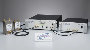
That depth of experience shapes the core advantage for modulation-sensitive programs: Lumistar's firmware-based, modular hardware architecture. The LS-18 and LS-19 product families—including the LS-18-R1 rack mount, LS-18-P1 portable, and LS-19-M RF test modulator—all support PCM/FM (Tier 0), SOQPSK-TG (Tier I), and Multi-H CPM (Tier II) on the same hardware platform. Modulation schemes can be changed via firmware post-delivery, without hardware modification or factory return.
The LS-28-DRSM series covers the ground station side: a compact receiver/combiner (6.00" × 4.00" × 1.67", under 1 kg, ~40 W typical) that demodulates PCM/FM, SOQPSK, Multi-H CPM, BPSK, QPSK, OQPSK, and more. An internal BER reader and PRN pattern generator support end-to-end modulation chain validation before range day. The LS-35-R IF receiver adds a built-in IF spectral display and constellation diagram, enabling in-field verification of spectral mask compliance.
Lumistar's specific differentiators for modulation-related decisions:
- End-to-end product line from RF transmission through ground reception and data display—enabling full chain validation before range day
- Adequate inventory maintained for short lead times on standard configurations
- Unlimited post-delivery technical support at no additional cost, with direct access to application engineers
- IRIG 106 Class I and II compliance verified across the transmitter product line
- Industry warranty coverage backed by a company whose products are in active use at federal test ranges across the country
Conclusion
No modulation scheme is universally optimal for telemetry transmitters. The right choice emerges from a disciplined evaluation of spectral constraints, required data rate, link margin budget, SWaP limits, IRIG 106 compliance, and—critically—what your ground station can actually demodulate.
Treat modulation selection as a program-level decision worth revisiting as data rate requirements grow, range infrastructure modernizes, or test vehicles change. A wrong choice discovered at integration is far more disruptive—and expensive—than one caught during requirements review.
Lumistar's engineering team brings over 100 years of combined telemetry experience to exactly these decisions—from modulation trade-offs to full transmitter-receiver compatibility across IRIG 106-compliant systems. Reach the team at sales@lumistar.net or call 760-431-2181.
Frequently Asked Questions
What modulation and multiplexing techniques do most telemetry systems use?
Most flight test telemetry systems use PCM/FM or SOQPSK-TG at the RF layer, combined with Time-Division Multiplexing (TDM) at the data layer. A commutator interleaves multiple sensor channels into a single serialized PCM bitstream (per RCC 106-24 Chapter 4) before that stream is modulated onto the carrier.
How does aeronautical telemetry modulation differ from satellite and aviation links?
Aeronautical telemetry primarily uses PCM/FM and SOQPSK-TG. Satellite downlinks typically favor BPSK or QPSK for their power efficiency over long distances, while aviation voice and data links rely on PM and FM variants. Each domain's modulation choice reflects its spectrum allocation, link distance, and hardware constraints.
What is modulation and why is it used in telemetry?
Modulation encodes information onto an RF carrier by varying its amplitude, frequency, or phase. Without it, baseband PCM data cannot be transmitted wirelessly across the distances typical of flight test operations—the signal would have no practical way to propagate through the atmosphere to a ground station.
What frequency bands are used for aeronautical telemetry?
The primary bands per RCC 106-24 Chapter 2 are lower L-band (1435–1525 MHz), lower S-band (2200–2290 MHz), upper S-band (2310–2395 MHz), and C-band extensions (4400–4940 MHz, 5091–5150 MHz). Band selection is governed by IRIG 106 and NTIA frequency coordination; higher bands offer wider bandwidth but require tighter antenna pointing and experience greater free-space path loss.
What are the different types of telemetry systems?
Aeronautical telemetry systems fall into two functional categories: airborne (sensor through transmitter and antenna) and ground (receiver through decommutator and display/archive). Within the airborne category, programs span fixed-wing aircraft, rotary-wing, UAVs, and expendable vehicles — each with different size, weight, and power constraints that shape system design.
What is the modulation index in RF communications?
The modulation index (h) defines the ratio of frequency deviation to bit rate in FM-based schemes like PCM/FM. RCC 106-24 recommends h = 0.7 for PCM/FM, giving a peak deviation equal to 0.35 times the bit rate. In phase modulation schemes, h represents peak phase deviation — and in both cases, the value directly sets occupied bandwidth.