Get it wrong in either direction and the consequences are costly. Choose an IF that is too low, and image rejection degrades while noise performance suffers. Choose one that is too high, and channel-selective filtering becomes impractical, ADC clock jitter sensitivity increases, and the component ecosystem thins out fast.
In aerospace and flight test environments, neither outcome is acceptable. This article breaks down the core trade-offs, the key selection factors, and how standard IF values align with real-world telemetry requirements under IRIG 106.
Key Takeaways
- IF frequency is the fixed internal frequency a superheterodyne receiver produces by mixing an RF carrier with a local oscillator signal
- Higher IF improves image rejection; lower IF improves channel selectivity. Optimizing both simultaneously isn't possible.
- Standard IF values (455 kHz, 10.7 MHz, 21.4 MHz, 70 MHz) have the strongest component ecosystems and lowest design risk
- 70 MHz is the documented professional telemetry IF, used in products from multiple manufacturers and supported by high-speed ADC datasheets
- IRIG 106 rejection minimums and channel bandwidth specs must drive IF selection alongside pure RF performance
What Is IF Frequency and Why Does the Choice Matter?
Analog Devices defines a superheterodyne receiver as one that mixes an incoming RF carrier with a local oscillator (LO) signal to produce an intermediate frequency that is easier to demodulate than the original carrier. That difference frequency — the IF — is where amplification, filtering, and detection occur — all at a stable, fixed value rather than at the original variable RF frequency.
What makes IF selection consequential is that the value is not defined by regulation or modulation standards. The system designer chooses it. That choice then dictates:
- Which filter technologies are physically practical
- How much gain can be applied before detection
- How well the receiver handles out-of-band interference
- Whether the ADC's dynamic range holds up at the target frequency
Consumer AM receivers standardize at 455 kHz and FM receivers at 10.7 MHz — both driven by decades of component commodity pricing. Flight test and aeronautical telemetry receivers are governed by performance requirements, not component economics — and they operate across a much wider range, with 70 MHz established as the standard in modern aeronautical telemetry systems. Quasonix RDMS receivers, for example, use a dual-conversion superheterodyne architecture with a 70 MHz second IF across bands spanning 200 MHz to 5250 MHz.
Understanding why 70 MHz became the telemetry standard — and what trade-offs it involves — starts with how IF frequency affects image rejection and filter selectivity.
The Core Performance Trade-offs IF Frequency Selection Drives
Every IF frequency decision is a negotiation between competing constraints. Understanding each trade-off individually makes the final selection defensible.
Image Rejection vs. Higher IF
The image frequency of a superheterodyne receiver sits at a distance of 2×IF from the desired RF signal. For high-side LO injection, the image appears at RF + 2×IF; for low-side injection, at RF − 2×IF.
The higher the IF, the farther the image sits from the desired channel, and the more attenuation the RF bandpass filter can provide before the signal reaches the mixer. In crowded S-band telemetry ranges where multiple aircraft transmit simultaneously, image signals can be strong enough to require 60–70 dB of image rejection — a level that Quasonix (70 dB) and SEMCO (>60 dB typical) confirm as the professional baseline.
IRIG 106 sets a minimum rejection floor of 60 dB for any frequency other than the tuned frequency across 150 kHz to 10 GHz. That level cannot be achieved by the IF filter alone at lower IF values. The RF preselection filter must do most of the work, which requires the IF to be high enough to give it separation room.
Selectivity vs. Lower IF
Keysight defines bandpass filter Q as the ratio of center frequency to bandwidth — higher Q means a narrower passband. This relationship is where low IF pays dividends: sharp channel-selective filters are physically much easier to realize at lower center frequencies because the required Q is proportionally lower.
Crystal and ceramic filters at 455 kHz, 10.7 MHz, and 21.4 MHz provide proven, cost-effective selectivity that would require impractically high Q at 70 MHz.
IRIG 106 specifies standard receiver IF bandwidths from 300 kHz to 20 MHz, with a filter shape requirement that the −60 dB bandwidth / −3 dB bandwidth ratio must be less than 3 for new designs. Meeting that shape factor is considerably easier at lower IF values with established filter technology.
1/f Noise and DC Offset at Low IF
At very low intermediate frequencies, Analog Devices notes that low-frequency 1/f (flicker) noise becomes a problem when insufficient gain is applied before downconversion — specifically when the signal drops below the process technology's 1/f corner frequency. DC offset voltages caused by LO self-mixing also become harder to filter without cutting into the desired passband.
No universal numeric lower IF bound applies to telemetry receivers; the threshold depends on the front-end gain plan and the semiconductor process used. In practice, receivers targeting noise figures below 5 dB typically avoid IFs below 10 MHz to keep both effects manageable without adding filtering complexity that narrows the usable passband.
Double Conversion as the Engineering Resolution
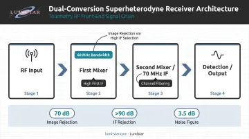
Analog Devices confirms that double conversion addresses both constraints simultaneously: a high first IF provides image rejection, while a lower second IF enables practical channel filtering. Distributing gain across two conversion stages also reduces oscillation risk in high-gain chains.
Quasonix RDMS receivers demonstrate this in production with a dual-conversion superheterodyne architecture delivering:
- 60 MHz first IF bandwidth for wideband image rejection
- 70 MHz second IF for channel filtering
- 70 dB image rejection and >90 dB IF rejection
- 3.5 dB typical noise figure
Key Factors for Choosing the Best IF Frequency
IF selection connects RF theory to real-world constraints. Engineers who optimize for only one factor typically encounter avoidable problems elsewhere. Here is what to evaluate systematically.
Image Rejection Requirements
Start with the RF environment. In a dense telemetry range, your image rejection requirement drives the IF floor, not your filter preferences.
- Determine the required rejection in dB based on expected interference sources
- Assess whether the RF bandpass filter can achieve that rejection at the candidate IF — if the image falls within the RF band, the preselector cannot help
- If the RF band is wide and rejection demands are severe, a high first IF (potentially above the RF band's upper edge) is often the only way to place the image outside the operating band entirely
Selectivity and Channel Bandwidth
Match the IF to what standard filter technology can actually deliver.
- 455 kHz, 10.7 MHz, and 21.4 MHz have robust ceramic and crystal filter ecosystems with well-characterized group delay — Murata's CERAFIL series covers 455 kHz and 10.7 MHz; ECS's 96SMF family covers 21.4 MHz
- 70 MHz SAW filters are commercially available (Spectrum Control's SF0070MF03053S, for example, provides a 4 MHz bandwidth with published phase linearity data)
- IRIG 106-compliant telemetry channels have defined deviation and bandwidth specifications — verify that the required noise bandwidth for your modulation scheme is achievable with available filters at the chosen IF before committing to it
ADC and Digital Processing Compatibility
In digital receivers, the IF you choose determines which ADC architecture is viable — and whether your dynamic range budget holds up.
- Direct sampling requires ADC sample rate ≥ 2×IF; bandpass sampling allows the IF to fold into the first Nyquist zone via sub-sampling
- ADC datasheets confirm 70 MHz as a documented use case: the AD6642 achieves 75.5 dBFS SNR in a 40 MHz band to 70 MHz at 185 MSPS; the AD9641 achieves 73.7 dBFS SNR at 70 MHz and 80 MSPS
- Clock jitter degrades SNR at higher input frequencies — Texas Instruments quantifies this as SNR_jitter = −20 log₁₀(2π × f_in × t_jitter); verify jitter-limited SNR at the candidate IF against your dynamic range budget
Component Availability and IRIG 106 Compliance
Standard IF values reduce design risk, schedule risk, and long-term supportability exposure. Non-standard IF frequencies may require custom filter design — a cost and schedule liability in flight test programs.
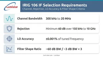
For aeronautical telemetry, IRIG 106 directly governs which IF choices are viable. Key requirements that affect IF selection include:
- Channel bandwidths from 300 kHz to 20 MHz
- Minimum 60 dB rejection over 150 kHz to 10 GHz
- LO accuracy within ±0.001% of indicated tuned frequency
- Filter shape ratio (−60 dB BW / −3 dB BW) < 3 for new designs
How Lumistar Can Help You Get IF Right
Selecting the right IF frequency involves trade-offs that vary by platform, RF band, and range environment — and getting it wrong shows up as degraded sensitivity, spurious responses, or BER performance that doesn't hold under real flight conditions. Lumistar's engineering team has navigated these decisions across hundreds of flight test programs since 2000, accumulating over 100 years of combined hands-on telemetry experience.
The LS-28-DRSM Series — a modular dual-channel receiving, combining, recording, and processing system — illustrates how IF architecture decisions translate into production hardware. The platform uses a fixed 70 MHz IF across all supported RF bands (P-band through C-band, 200 MHz to 7 GHz), providing three independent 70 MHz IF outputs for CH1, CH2, and Combined.
Key IF-related specifications of the LS-28-DRSM:
- Eight hardware SAW filters at 0.25, 0.5, 1, 2, 5, 10, 20, and 40 MHz bandwidths
- 40,000+ digital FIR filter selections with 10 kHz resolution, auto-optimized by data rate, PCM code, and modulation format
- 4 dB typical noise figure with 120 dB instantaneous dynamic range
- Firmware-configurable demodulation formats — PCM/FM, SOQPSK, BPSK, QPSK, OQPSK, and more — without hardware redesign
- Integrated 70 MHz IF modulator for loopback testing and BER validation
The firmware-based architecture means IF bandwidth parameters adapt to mission requirements electronically. Firmware license files expand base configurations as requirements evolve, with no hardware modifications needed.
That flexibility extends to post-delivery support. Lumistar provides unlimited technical support with direct access to application engineers on the first call — no support queue, no ticket system. Engineers troubleshooting IF-related issues or planning a new system integration reach the team directly.
For IF architecture guidance, receiver selection support, or questions about IRIG 106 compliance for a specific range environment, contact the Lumistar sales team at sales@lumistar.net or call 760-431-2181.
Conclusion
Selecting the right IF frequency means balancing image rejection, channel selectivity, noise performance, and ADC compatibility against the real constraints of available components and applicable system standards. No single frequency works for every receiver — the right choice depends on your specific architecture and program requirements.
IF decisions made early in receiver design are difficult to reverse later. Before committing to hardware, validate against:
- Image rejection budget
- Noise figure budget
- ADC SNR budget
For programs operating under IRIG 106, confirm the IF architecture supports the required channel bandwidths and rejection specifications — with specific filter parts verified on the BOM, not just modeled in simulation.
Frequently Asked Questions
What is an IF receiver?
An IF receiver (specifically a superheterodyne receiver) converts an incoming RF signal to a fixed intermediate frequency before amplification, filtering, and detection. Filters and amplifiers optimized for one fixed frequency deliver far better performance than components that must cover a wide RF tuning range — which is why this architecture dominates professional radio design.
What's the difference between RF and IF?
RF is the transmitted or received carrier frequency — it varies depending on the signal source and channel. IF is the fixed internal frequency the receiver's mixer produces from that RF signal. IF processing is more practical because every stage in the IF chain can be precisely engineered for one frequency rather than an entire band.
Why is 455 kHz used as an IF?
455 kHz offered a practical balance of selectivity and image rejection for medium-wave AM broadcast bands in early superheterodyne designs. That widespread adoption created a durable supply chain of low-cost ceramic filters and IF transformers still available today, even as professional receivers have moved to much higher IF values.
What is an IF output?
The IF output is the downconverted signal available at the intermediate frequency stage — often tapped before the detector — that can feed an external spectrum analyzer, a second conversion stage, or an IF digitizing subsystem for further processing. Lumistar's LS-28-DRSM, for example, provides three independent 70 MHz IF outputs.
What is double conversion in a superheterodyne receiver?
Double conversion uses two sequential downconversions: a high first IF for image rejection and a lower second IF for channel selectivity. Neither IF alone can achieve both objectives simultaneously, so the dual-stage architecture is the standard approach in professional telemetry and communications receivers.
How does IF frequency affect receiver sensitivity?
IF frequency affects sensitivity through three mechanisms:
- Very low IF raises 1/f noise contributions from active components
- IF filter insertion loss adds directly to the noise figure
- At high IF, ADC clock jitter degrades SNR in proportion to input frequency
Balancing all three is the core engineering challenge of IF frequency selection.