Introduction
RF engineers working on aerospace and defense systems face a persistent tension: telemetry receivers need to cover wider frequency ranges, handle more channels simultaneously, and fit into ever-smaller platforms — all without compromising signal integrity. Traditional heterodyne architectures rely on mixers, local oscillators, and IF filter chains — a combination that struggles to meet these demands at scale.
Direct RF sampling addresses this directly. Replacing the mixer and LO with a high-speed ADC compresses a lengthy analog signal chain into far fewer components, reducing SWaP, simplifying multi-channel synchronization, and enabling software-defined reconfigurability that heterodyne designs can't match.
What follows breaks down how direct RF sampling works, where it outperforms heterodyne designs, the trade-offs engineers actually encounter, and how this architecture applies to modern flight test telemetry — including Lumistar's LS-28-DRSM series, which brought direct RF sampling into production ground station deployments.
Key Takeaways
- Direct RF sampling ADCs digitize signals at RF frequency, eliminating the mixer, LO, and IF stages of traditional heterodyne receivers
- Simplified hardware reduces component count and SWaP, benefiting airborne pods, portable ground stations, and phased arrays
- No LO means no LO leakage, no I/Q imbalance, and no mixing-image interference
- Multi-channel synchronization reduces to clock alignment only — no LO phase matching required
- Key trade-offs: higher ADC power draw, demanding RF-frequency anti-aliasing filters, and significant clock jitter sensitivity at high input frequencies
What Is a Direct RF Sampling Receiver?
The Core Architecture
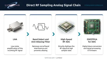
A direct RF sampling receiver uses a high-speed ADC to digitize an incoming RF signal without first converting it to an intermediate frequency. The ADC output goes straight to a digital signal processor — typically an FPGA — which handles filtering, channel selection, image rejection, and demodulation in the digital domain.
The analog signal chain is minimal:
- Low-noise amplifier (LNA)
- Band-select and anti-aliasing filter
- High-speed RF ADC
- DSP/FPGA for digital down conversion (DDC)
This is distinct from a zero-IF (direct conversion) receiver, which mixes the signal to baseband before digitization. Direct RF sampling retains the signal at RF frequency all the way through the ADC — the frequency conversion happens digitally.
What Made It Practical
A decade ago, digitizing signals directly at L- or S-band required ADC technology that didn't yet exist at usable cost and power. That's changed substantially. Texas Instruments documented a 4 GSPS RF-sampling ADC in 2015; by 2025, their ADC12DJ5200RF runs at 10.4 GSPS single-channel with input bandwidth extending above 10 GHz.
Analog Devices took a parallel path — their AD9208 (2017) delivers 3 GSPS operation across a 9 GHz analog input bandwidth, targeting wideband receiver applications directly.
These sample rates place L-band (1435–1535 MHz) and S-band (2200–2390 MHz) telemetry frequencies — the primary bands defined in IRIG 106-20 Chapter 2 for aeronautical mobile telemetry — well within the first or second Nyquist zone of current-generation RF ADCs.
DSP Replaces Analog Functions
Those ADC sample rates make the analog front end largely irrelevant for frequency planning. Once the signal is digitized, the FPGA handles DDC, channel isolation, filtering, and demodulation entirely in firmware.
The receiver becomes software-reconfigurable. Changing frequency bands, modulation formats, or processing algorithms is a firmware update — not a board redesign.
Direct RF Sampling vs. Traditional Heterodyne Architecture
Heterodyne Signal Chain
The classic heterodyne receiver distributes the signal processing across multiple frequency stages:
Antenna → bandpass filter → LNA → SAW filter → mixer + LO → IF amplifier → anti-aliasing filter → ADC
Each stage serves a purpose. The mixer translates the RF signal to a lower intermediate frequency where filters are easier to implement and ADC requirements are less demanding. Gain is distributed: approximately 32 dB at RF and 18 dB at baseband, per Analog Devices' architecture comparison.
The trade-off is complexity. The mixer introduces I/Q gain and phase mismatch, producing unwanted signal images on the opposite side of the LO frequency. LO leakage contaminates the signal path. SAW filters are required to suppress these mixing artifacts. Each additional band needs its own front-end chain.
Direct RF Sampling Signal Chain
That per-band front-end complexity is precisely what direct RF sampling eliminates.
Antenna → LNA → anti-aliasing/band-select filter → RF ADC → FPGA/DSP
All gain resides in the RF domain — approximately 50 dB — with nothing at baseband. The ADC performs the frequency conversion digitally through DDC, replacing the mixer and LO entirely.
The architectural differences produce measurable trade-offs across several key parameters:
| Parameter | Heterodyne | Direct RF Sampling |
|---|---|---|
| Gain distribution | RF (~32 dB) + baseband (~18 dB) | RF only (~50 dB) |
| Frequency conversion | Analog mixer + LO | Digital DDC |
| Image rejection | SAW filters + I/Q correction | Frequency planning + anti-alias filters |
| Multi-channel LO sync | Required | Not applicable |
| Spurious signals | LO leakage, mixing images | Interleave spurs, aliasing terms |
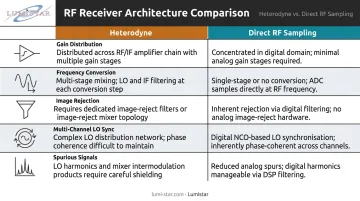
The spurious signal row deserves attention. Where heterodyne designs contend with LO leakage and mixing images, direct RF sampling trades those problems for interleave spurs — artifacts caused by offset, gain, and timing mismatches between the ADC's interleaved sub-channels. Modern RF ADCs address this through background calibration and digital correction, but frequency planning remains a design discipline in both architectures, not an afterthought exclusive to one.
Key Advantages of Direct RF Sampling Receivers
Reduced SWaP and Hardware Simplicity
Removing the mixer, LO, IF amplifier, SAW filters, and associated passive components dramatically shrinks the BOM. This matters most where space is genuinely constrained — antenna pedestal feed assemblies, airborne test pods, man-portable ground stations.
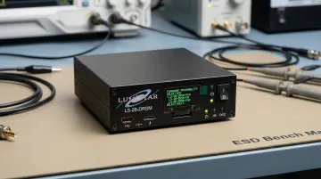
The LS-28-DRSM from Lumistar illustrates what this compression looks like in practice. The modular unit measures 6.00" × 4.00" × 1.67", weighs under 1 kg, and delivers complete dual-channel RF reception with diversity combining, multi-mode demodulation, and Ethernet data output. A complete portable version fits in a carry-on lunchbox case.
No LO-Related Signal Impairments
Three specific heterodyne impairments disappear entirely when the LO is eliminated:
- LO leakage: In a heterodyne receiver, LO signal bleeds into the RF path, creating a tone at the LO frequency that degrades receiver noise floor and dynamic range
- I/Q imbalance: Gain and phase mismatch between I and Q mixing paths creates an unwanted mirror image of the desired signal at the opposite side of the LO frequency
- Mixing images: Any signal at the image frequency folds directly onto the desired signal after mixing, requiring SAW filters to reject it before the mixer
Direct RF sampling eliminates all three mechanisms. There is no LO to leak, no quadrature mixing to balance, and no image frequency created by the mixing process.
Simplified Multi-Channel Synchronization
Phase coherence across multiple receiver channels requires synchronizing everything that contributes to phase. In a heterodyne system, that means both the sampling clock and the local oscillator on every channel — a non-trivial problem when scaling to dozens of channels.
Direct RF sampling removes the LO from the synchronization equation entirely. Achieving coherence across channels reduces to clock alignment only, which is far more manageable. For phased array radar systems with 16, 64, or hundreds of elements, this simplification is significant. Analog Devices demonstrated a 16 Tx / 16 Rx channel direct sampling phased array system for radar and EW at Phased Array 2022, illustrating the architecture's viability at scale.
Wideband and Multi-Band Capture
Current RF ADCs can simultaneously capture wide swaths of spectrum across multiple bands. The TI ADC12DJ5200RF provides 10.4 GSPS with 8 GHz analog input bandwidth — enough to cover L-band, S-band, and C-band telemetry frequencies simultaneously from a single converter. A heterodyne receiver covering the same frequency range would require a separate front-end chain for each band.
Software-Defined Flexibility
Because all channel selection, filtering, and demodulation happen in FPGA firmware, the receiver's functional behavior is determined by firmware rather than hardware. New modulation formats, signal processing algorithms, or frequency configurations become firmware updates.
Lumistar calls these firmware personalities in the LS-28-DRSM context. A single hardware unit switches between licensed firmware files without any physical hardware change — for example:
3PCMFM_RCVR— three-channel PCM/FM personality3MHCPM_RCVR— Multi-H CPM personality- PSK receiver with LDPC forward error correction
For flight test programs with evolving signal formats or multi-program hardware requirements, this means one procurement covers years of operational changes.
Technical Challenges and Design Trade-offs
Power Consumption at High Sample Rates
A multi-GSPS ADC consumes substantially more power than a baseband converter processing only the signal bandwidth. Dynamic power dissipation scales with switching frequency and capacitive load — running at 3–10 GSPS carries a real power penalty.
TI's 2015 analysis quantified this: RF converter cores consume approximately 125% more power than baseband converters for a single-band implementation and more than 40% more even when digitizing two bands. Reference designs confirm the numbers — the TI ADC12DJ5200RF draws 4 W typical at 10.4 GSPS; the ADI AD9208 draws 3.3 W at 3 GSPS.
Those numbers don't tell the whole SWaP story. Direct RF sampling eliminates the mixer, LO, and IF chain — and the power those components consumed must be weighed against the higher ADC draw. For single-band applications, heterodyne may retain a power advantage. For multi-band or wideband applications, direct RF sampling becomes more competitive.
Clock Jitter and SNR Degradation
Jitter in the sampling clock creates timing uncertainty at the ADC sampling instant, which translates directly to SNR degradation. Per ADI's MT-007 tutorial, the jitter-limited SNR for a full-scale sine wave is:
SNR ≈ −20 log₁₀(2π × f_in × σ_t)
Where f_in is the input RF frequency and σ_t is the total RMS jitter. The critical point is that SNR degradation scales with input frequency — 100 fs RMS jitter that is acceptable at 100 MHz becomes a serious problem at 2 GHz or 5 GHz.
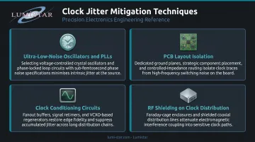
Designers address this through:
- Ultra-low-noise clock oscillators and PLLs
- Careful PCB layout isolating clock traces from digital switching noise
- Clock conditioning circuits (jitter attenuators, frequency multipliers with low phase noise)
- RF shielding around the clock distribution network
Anti-Aliasing Filter Complexity
Because the ADC operates within Nyquist zones, any signal in an alias band folds directly into the desired band. Rejecting those signals requires aggressive anti-aliasing filtering, and at RF frequencies filter design is considerably harder than at IF.
RF filters must achieve steep roll-off while maintaining low insertion loss at the desired band edge — at frequencies where parasitic effects are larger and component tolerances tighter. ADI's architecture comparison notes that some RF-sampling scenarios require cavity filter rejection exceeding 125 dB.
Careful sampling clock selection can reduce this burden significantly. By choosing the clock frequency to place the desired signal in a favorable Nyquist zone relative to potential interferers, designers minimize alias overlap. It doesn't eliminate filtering requirements, but it does make them manageable.
Applications in Aerospace, Defense, and Flight Test Telemetry
Radar, Electronic Warfare, and SIGINT
Per-channel SWaP reduction and simplified synchronization make direct RF sampling architectures well-suited for phased array radar. All-digital beamforming requires independent ADC access to each antenna element — an architecture that becomes practical only when each receiver channel is small and coherence is achievable. ADI's 16×16 phased array demonstration at Phased Array 2022 represents the current state of the art in deployed demonstrations. AMD's Versal RF Adaptive SoCs take a similar approach, integrating wideband RF data converters with programmable logic for X-band-relevant radar and EW designs.
For SIGINT and spectrum monitoring, the wideband capture capability is the primary value. A single direct RF sampling receiver can simultaneously monitor spectrum across hundreds of megahertz or multiple gigahertz of bandwidth. A heterodyne receiver must tune sequentially — meaning any signal present during the tuning interval is missed. For threat detection or spectrum awareness applications, that gap is operationally significant.
Flight Test Telemetry
Aeronautical flight test ground stations receive IRIG 106-compliant telemetry from moving test articles across L-band (1435–1535 MHz) and S-band (2200–2290 MHz and 2310–2390 MHz). The receiver needs to track the signal across those bands, handle multi-path fading with diversity combining, and deliver clean bit-sync data to downstream processing — in a package that can deploy at remote range locations or integrate into a tracking antenna system.
Covering multiple bands from a single front-end while eliminating the analog IF chain produces a dramatically smaller form factor — and that's exactly the problem Lumistar's LS-28-DRSM series was designed to solve.
Two form factors address different deployment scenarios:
- Modular (LS-28-DRSM): Roughly the size of a hard drive (6" × 4" × 1.67", under 1 kg), integrates directly into antenna pedestal feed assemblies, covers L-band through C-band (200 MHz to 7 GHz) with dual-channel diversity combining
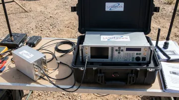
- Portable (P1): A complete telemetry ground station in a waterproof case weighing approximately 15 pounds, with 10 hours of battery life for remote range deployment
Firmware personalities — PCM/FM, SOQPSK, Multi-H CPM, BPSK, QPSK, and PSK with LDPC — can be loaded or upgraded in the field without hardware changes, covering the full range of IRIG 106-compliant waveforms used in flight test.
Frequently Asked Questions
What is the difference between a direct RF sampling receiver and a heterodyne receiver?
A heterodyne receiver downconverts the RF signal to an intermediate frequency using a mixer and local oscillator before digitization. A direct RF sampling receiver uses a high-speed RF ADC to digitize the signal at its original RF frequency, eliminating the mixer, LO, and IF stages entirely. Frequency conversion and channel selection happen digitally in the DSP.
Is direct RF sampling the same as zero-IF or direct conversion?
No. A zero-IF receiver mixes the RF signal down to baseband (near DC) before digitizing. A direct RF sampling receiver digitizes the signal while it's still at RF frequency: the ADC sees the full RF carrier. Both architectures eliminate a traditional IF stage, but through different mechanisms — with different trade-offs for filtering complexity and DC offset behavior.
What are the main disadvantages of direct RF sampling?
Three primary trade-offs come with this architecture:
- Higher ADC power consumption at multi-GSPS sample rates
- Demanding anti-aliasing filter requirements at RF frequencies (vs. easier IF filtering in heterodyne designs)
- Significant SNR sensitivity to sampling clock jitter, which worsens as input RF frequency increases
How does clock jitter affect direct RF sampling performance?
Clock jitter introduces timing uncertainty at each ADC sampling instant, which degrades SNR according to the relationship SNR ≈ −20 log₁₀(2π × f_in × σ_t). Because SNR degradation scales directly with input frequency, even femtosecond-level jitter becomes problematic at S-band and above, making ultra-low-noise clock sources essential.
What ADC specifications are most critical for a direct RF sampling design?
The key specifications are sample rate (determines which Nyquist zone the target band falls in), effective number of bits/SNR (sets receiver sensitivity), spurious-free dynamic range (SFDR), and interleave spur performance in time-interleaved architectures.
What applications benefit most from direct RF sampling?
Applications with SWaP constraints, wide instantaneous bandwidth requirements, or multi-channel phase coherence needs benefit most. This covers phased array radar, electronic warfare, SIGINT, spectrum monitoring, and aeronautical flight test telemetry — anywhere simultaneous wideband coverage, software reconfigurability, or compact packaging drive the design.