This post covers the core mechanics of radio telemetry, its three essential components, the major application domains, and how the technology has evolved — with particular focus on aerospace and flight test, where the demands on these systems are most rigorous.
While wildlife researchers and clinicians use radio telemetry daily, the most technically complex implementations occur in aerospace, defense, and flight test. In those environments, data accuracy isn't a convenience — it's a safety and mission requirement.
Key Takeaways
- Radio telemetry automatically collects sensor measurements and transmits them wirelessly to a receiving station — no wires, no on-site personnel required
- Every system has three core components: a transmitter at the source, an antenna to carry the signal, and a receiver/ground station to decode and record data
- Applications range from wildlife tracking and patient monitoring to environmental sensing and aerospace flight test
- Flight test telemetry operates under IRIG 106, the Range Commanders Council standard for frequency use, modulation, PCM formatting, and range interoperability
What Is Radio Telemetry and How Does It Work?
NASA defines radiotelemetry as the automatic measurement and transmission of data by radio from remote sources to receiving stations for recording and analysis. The FCC's regulatory definition is similar: telemetry is telecommunication for automatically indicating or recording measurements at a distance; radiotelemetry is telemetry by radio waves.
Neither definition mentions conversation — and that distinction matters. Radio telemetry is a measurement-data discipline, not a communications service.
The Signal Flow
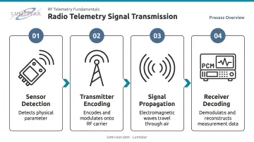
The path from sensor to data record follows four steps:
- Sensors detect a physical parameter — position, temperature, pressure, vibration, airspeed — and produce an electrical signal proportional to the measurement
- The transmitter encodes and modulates that signal onto a radio frequency carrier wave
- The signal propagates through the air as electromagnetic waves until it reaches a receiving antenna
- The receiver demodulates and decodes the incoming signal, reconstructing the original measurement data for display, recording, and analysis
Frequency Band Selection
The frequency band a system uses depends on range requirements, data rate, and the operating environment. Aeronautical telemetry uses IRIG-designated bands to ensure interoperability across test ranges:
- Lower L-band: 1435–1525 MHz (primary AMT allocation per FCC 47 CFR 87.303)
- S-band: 2200–2290 MHz and 2310–2395 MHz
- C-band: 4400–4940 MHz and 5091–5150 MHz
Wildlife telemetry commonly uses VHF bands around 150–220 MHz. Medical telemetry operates in FCC-designated WMTS bands at 608–614 MHz and 1395–1432 MHz.
One-Way vs. Two-Way
Beyond frequency selection, the directional architecture of a telemetry link defines how data moves through the system.
Radio telemetry is a one-way data pipeline — sensors report to a receiver that does not talk back. Two-way radio systems let both parties send and receive; telemetry only flows one direction. Some advanced aerospace configurations pair a telemetry downlink with a separate command uplink, but the telemetry data path stays unidirectional.
The Three Core Components of a Radio Telemetry System
Transmitter
The transmitter is the originating node — housing a power source, sensor or data interface, signal encoder, and antenna. Design parameters vary sharply by application:
- Wildlife tracking: Weight dominates. Tags must stay under roughly 5% of the animal's body weight, pushing designers toward miniaturized batteries and low-power circuits
- Flight test: The constraints shift to vibration tolerance, form factor, and data throughput. Airborne transmitters must handle multi-channel PCM (Pulse Code Modulation) streams encoding dozens of flight parameters simultaneously — airspeed, altitude, structural loads, engine performance — rather than simple location pulses
IRIG 106 Chapter 4 defines the PCM pulse-train structure governing these aeronautical transmitters — specifying binary bit representation, minor and major frames, and fixed synchronization patterns that receivers must recognize.
Antenna
Once the transmitter encodes the data, the antenna takes over as the physical interface between electronics and the propagating radio wave. Antenna type determines directionality:
- Omnidirectional: Radiates and receives in all directions — practical for animals or slowly maneuvering aircraft
- Directional (Yagi arrays, parabolic dishes): Focuses gain in a specific direction, extending range and improving signal strength
Ground-based aeronautical telemetry stations use motorized tracking antennas that actively follow a fast-moving test aircraft. These systems require sophisticated auto-tracking algorithms and pedestal servo control to maintain link quality throughout a flight test mission. Receivers designed for this role — such as Lumistar's LS-27-M Series — provide the programmable AGC and AM outputs that drive antenna positioner systems, with multiple software-selectable lowpass filters for precise tracking control.
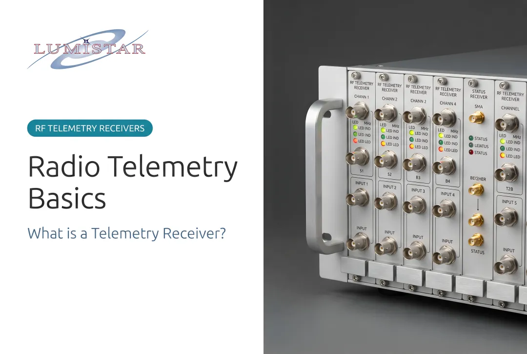
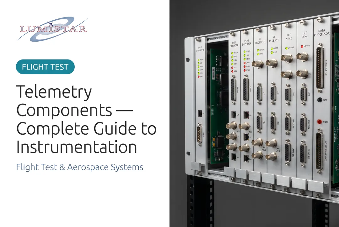
Receiver and Ground Station
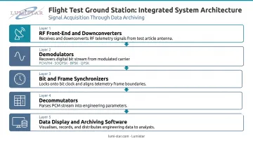
The receiver decodes and captures the incoming data. Basic receivers convert an RF signal to a tone or readout. Flight test ground stations are considerably more complex. They integrate:
- RF front-end components and downconverters
- Demodulators supporting PCM/FM, SOQPSK, BPSK, QPSK, and other waveforms
- Bit synchronizers and frame synchronizers
- Decommutators that parse the PCM stream into individual engineering parameters
- Data display and archiving software
IRIG 106 Chapter 4 requires that receivers handle fixed synchronization words, proper framing, and sufficient bit transitions to support reliable symbol recovery — requirements that go well beyond what a standard two-way radio receiver needs.
Key Applications of Radio Telemetry Across Industries
Wildlife and Ecological Research
Scientists attach small VHF transmitters to animals to study movement, migration, habitat use, and population dynamics. Researchers locate animals by sweeping directional antennas to home in on the signal, or by triangulating across multiple stations.
The Motus Wildlife Tracking System demonstrates what automated multi-station networks can achieve: 2,055 receiving stations, 402 species tagged, 50,932 animals tagged, across 34 countries and 887 active projects — effectively a continental-scale migration data network built on radio telemetry principles.
Healthcare and Patient Monitoring
Medical telemetry attaches biosensors to patients and transmits vital signs (heart rate, blood pressure, oxygen saturation) to nursing stations or remote monitoring centers. The FCC established the Wireless Medical Telemetry Service (WMTS) with 14 MHz of dedicated spectrum across three bands, specifically to protect patient monitoring signals from interference.
Environmental and Industrial Monitoring
Remote weather stations, flood monitoring networks, pipeline sensors, and SCADA infrastructure use radio telemetry to transmit data from locations where running cables is impractical or impossible. CISA identifies 16 US critical infrastructure sectors (energy, water, transportation, and others) where SCADA and telemetry systems underpin national security and economic function. The SCADA market was valued at roughly $12 billion in 2024, a figure that reflects how broadly industrial telemetry has penetrated critical infrastructure.
Aerospace and Flight Test
Test aircraft, missiles, and launch vehicles carry onboard instrumentation packages that stream dozens to hundreds of flight parameters in real time to ground stations. Engineers monitor these streams live to assess performance, structural integrity, and flight safety — calling off a test the moment anomalous data appears. Aerospace flight test is where radio telemetry operates at its most demanding.
The scale of federal flight test operations puts the requirement in context: the Air Force Test Center is a $31 billion enterprise with more than 18,000 personnel, and NAWCAD's Atlantic Test Ranges encompass 2,700 square miles of restricted Chesapeake airspace plus 57,000 square miles of offshore air and sea space. Every parameter from every test vehicle on those ranges flows through telemetry systems that must comply with IRIG 106.
Defense and Range Operations
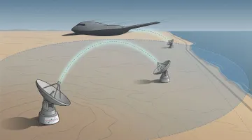
Military test ranges use radio telemetry to track test articles (drones, munitions, re-entry vehicles) and collect performance data under operational conditions. Multi-station range networks provide overlapping coverage to ensure continuous data capture throughout a test vehicle's trajectory, regardless of viewing angle or signal blockage from any individual station.
Key capabilities these networks support include:
- Continuous trajectory coverage with no single point of signal failure
- Real-time data capture across extended flight envelopes
- Post-flight reconstruction of full mission timelines from multi-station data
Advantages and Limitations of Radio Telemetry
Key Advantages
- Access to the inaccessible: Collects data from fast-moving test aircraft, deep wilderness, underground pipelines, and other locations where physical access is impractical or dangerous
- Autonomous operation: Logs data continuously without on-site personnel, critical when a test profile runs for hours across hundreds of miles
- Real-time visibility: Enables immediate decisions — in flight test, a safety anomaly must be detected and acted upon in seconds, not after landing
Practical Limitations
- Range constraints: Transmitter power, antenna gain, terrain, and atmospheric conditions all cap how far a signal travels reliably
- Battery life: Miniaturized wildlife tags face hard tradeoffs between transmission power and operational duration
- Spectrum coordination: Frequency spectrum is shared and regulated. Active test ranges with multiple simultaneous transmitters require careful coordination to prevent interference
Data Integrity Challenges
Multipath interference — signals bouncing off terrain or structures — can corrupt a telemetry stream. The standard mitigation in aeronautical telemetry is spatial diversity: two or more receive antennas at different locations capture independent signal copies, then combine them to reduce fading effects.
Research presented at ITC 2021 found that approximately 5 meters of vertical offset between receive antennas reduces bit error rates at low elevation angles. RCC 118-12 Volume 2 defines the acceptance tests for diversity combiners, covering both static and dynamic fading simulation.
The Evolution of Aerospace Radio Telemetry Systems
From Racks to Handhelds
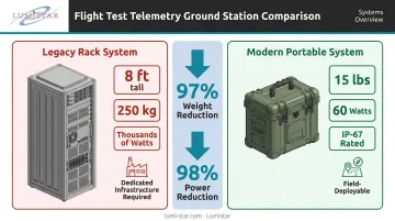
Less than 20 years ago, a typical flight test telemetry ground station was 8 feet tall, weighed 250 kg, consumed thousands of watts, required dedicated facility infrastructure, and was difficult to operate. Advances in RF integrated circuits, digital signal processing, and firmware-based architectures have changed that picture dramatically.
Lumistar's LS-28-DRSM-P1 — a complete portable ground station with dual-channel RF reception from 200 MHz to 6 GHz, diversity combining, demodulation, bit synchronization, frame synchronization, decommutation, and data recording — fits in an IP-67 rated lunchbox case weighing 15 pounds and consuming 60 watts. The most compact modular configuration comes in under 1 kg and 50 watts.
That's roughly a 97% reduction in weight and more than 98% reduction in power consumption compared to the legacy rack systems, with better reliability and simpler operation.
What That Enables
That SWaP reduction directly expands what's operationally possible in the field:
- Mobile and expeditionary deployments at forward locations without dedicated facilities
- Shipboard operations in maritime test environments
- Chase plane integration for airborne data relay
- Antenna pedestal mounting of the receiver directly at the feed for reduced cable loss
Lumistar's LS-28-DRSM series uses a firmware-based personality architecture, meaning a single hardware platform can be reconfigured for different operational modes — demodulator, tracking receiver, diversity combiner, PCM processor — without hardware changes. Capabilities can be added via firmware upgrade in the field.
Standards Continuity
Smaller hardware doesn't mean relaxed compliance. Modern telemetry systems must still conform to IRIG 106 for frequency use, modulation methods, PCM formatting, bit and frame synchronization, and interoperability across test ranges and programs.
IRIG 106-23 extends that framework with networked telemetry chapters (Chapters 21–28) covering Telemetry Network Standards and RF Network Management. These address the industry's move from classic point-to-point PCM downlinks to IP-based range architectures, while preserving backward compatibility.
Frequently Asked Questions
What does a radio telemetry unit do?
A radio telemetry unit collects data from onboard sensors and transmits those measurements wirelessly via RF signal to a remote receiver for monitoring, recording, and analysis — without physical wires or on-site personnel at the data source.
What frequency is used in radio telemetry?
It depends on the application. Wildlife telemetry uses VHF bands around 150–220 MHz. Aerospace and flight test telemetry uses IRIG-designated L-band (1435–1525 MHz) and S-band (2200–2395 MHz). Airborne PCM telemetry systems may also operate in UHF ranges depending on range and bandwidth requirements. Each band involves tradeoffs between range, data rate, and antenna size.
What is the difference between telemetry and two-way radio communication?
Telemetry is a one-way data pipeline from sensors to a receiver, designed to transmit structured measurement data automatically and continuously. Two-way radio enables interactive voice or data exchange between people or systems. Telemetry receivers also require specialized demodulation, bit synchronization, and frame synchronization hardware that standard two-way radios do not.
How far can a radio telemetry signal travel?
Range depends on transmitter power, antenna gain, frequency, and terrain. A compact airborne transmitter on a UAV may cover only a few miles, while ground-based aeronautical stations with high-gain tracking antennas can maintain a reliable link with a fast-moving test aircraft across dozens to hundreds of miles under line-of-sight conditions.
What is IRIG 106 in the context of radio telemetry?
IRIG 106 is the telemetry standards document published by the Range Commanders Council, governing frequency allocations, modulation types, PCM data formats, and synchronization requirements for aeronautical and range telemetry systems. It ensures interoperability across military and civilian test ranges. The current version, IRIG Standard 106-23, was prepared by the RCC Telemetry Group and published by the Secretariat at White Sands Missile Range.