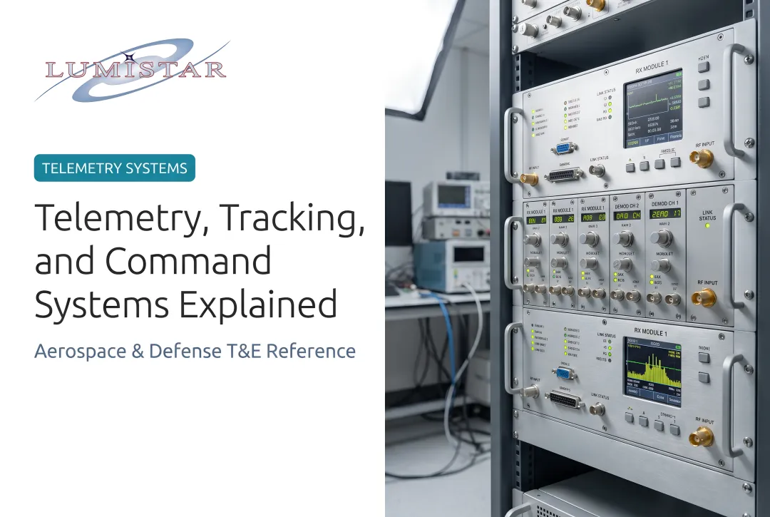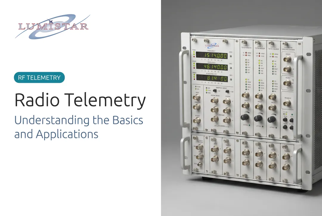
This guide covers the full hardware stack of an aeronautical telemetry system, from sensors bolted to the test article through to the ground station workstations displaying live engineering values. One clarification upfront: this is flight test telemetry — governed by IRIG 106 and built on dedicated RF hardware — not IT observability, medical monitoring, or industrial IoT.
Key Takeaways
- A telemetry system splits into two subsystems: airborne instrumentation (sensors through RF transmitter) and a ground station (antenna through data display).
- Data flows from physical measurement → PCM encoding → RF transmission → ground reception → decommutation → real-time engineering display.
- IRIG 106 defines the PCM formats, modulation schemes, and recording standards that keep multi-vendor equipment interoperable.
- Modern systems have shrunk dramatically — complete ground stations that once filled an 8-foot rack at 250 kg now fit in a handheld unit under 1 kg.
- Correct component selection and end-to-end integration are what separate reliable flight data from costly dropouts.
What Is Telemetry Instrumentation?
In the aeronautical context, telemetry instrumentation is the complete system of hardware and software that:
- Measures physical parameters on a test article
- Encodes that data into a digital stream
- Transmits it over an RF link
- Receives, processes, and displays it at a ground station in real time
This is distinct from other domains that use the word "telemetry." IT teams use it for software observability. Medical professionals use it for patient monitoring. Both rely on internet protocols and commercial networks. Aeronautical telemetry operates on dedicated RF links, follows strict RCC standards, and must function when no network infrastructure exists — over open ocean, at altitude, or in a weapons range.
Why Real-Time Matters
Onboard recorders are valuable, but they're not sufficient on their own. NASA's development flight instrumentation research illustrates why: for unrecoverable launch vehicle stages that splash down and sink, real-time telemetry is the only path data has to reach the ground before hardware is lost.
In one Ares I-X case, the final 90 seconds of buffered data were lost when power cut at ocean impact — a gap that real-time downlink would have filled.
The stakes shift for crewed test aircraft, but the dependency doesn't. Range safety officers and chase engineers rely on live feeds to make immediate decisions during envelope expansion — there's no waiting for post-flight data retrieval.
The Core Components of a Telemetry System
Every flight test telemetry system has two major subsystems that must be matched and calibrated to work together: the airborne instrumentation system and the ground receiving and processing station.
Airborne Instrumentation Components
Sensors and transducers are the starting point. They convert physical phenomena — pressure, temperature, vibration, acceleration, strain, electrical voltages — into electrical signals. The NASA Ares I-X program illustrates the scale this can reach: the final development flight instrumentation configuration included 901 measurements from 716 sensors, transmitting at 10.1 Mbps on the DFI link alone.
Signal conditioners and PCM encoders prepare those raw sensor outputs for transmission. Signal conditioning amplifies, filters, and normalizes the signals. A PCM (Pulse Code Modulation) encoder then multiplexes all channels into a single serial digital data stream. IRIG 106-20 Chapter 4 defines this stream precisely:
- Serial binary-coded, time-division multiplexed words
- Class I word lengths: 4 to 32 bits
- Class II covers more complex cases: bit rates above 10 Mbps, word lengths above 32 bits, fragmented words
- Minor-frame sync pattern: 16 to 33 consecutive bits
The encoder's frame structure, sample rate, and word length must be designed to the specific test objectives — each test program defines its own requirements.
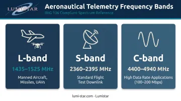
RF transmitter and onboard antenna close the airborne side of the link. The transmitter modulates the PCM stream onto an RF carrier. The primary aeronautical telemetry (AMT) bands are:
| Band | Frequency Range | Primary Use |
|---|---|---|
| L-band | 1435–1525 MHz | Manned aircraft, missiles, UAVs |
| S-band | 2360–2395 MHz | Standard flight test downlink |
| C-band | 4400–4940 MHz | High data rate applications (100–200 Mbps) |
Antenna placement is critical. The onboard antenna (typically a blade or conformal design) must maintain adequate link margin across all expected flight attitudes, including inverted and high-angle-of-attack maneuvers.
Ground Station Components
Receiving antenna systems are the first element in the ground chain. Fixed omni antennas work for short-range or confined test areas. For longer ranges, parabolic dish antennas (IRIG 106-20 Chapter 2 models dishes from 2.44 meters to 10 meters) track the aircraft automatically using azimuth/elevation drives. Antenna gain directly determines the usable range of the telemetry link.
RF receiver and preamplifier amplify the weak incoming signal. A low-noise preamplifier (LNA) at the antenna feed handles the first amplification stage, where every decibel of noise figure counts. The receiver then demodulates the signal to recover the baseband PCM data stream. Key receiver parameters (noise figure, dynamic range, acquisition threshold) determine the system's sensitivity floor.
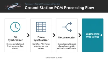
Bit synchronizer, frame synchronizer, and decommutator are three sequential processing steps:
- Bit synchronizer — recovers the digital clock from the incoming data stream
- Frame synchronizer — identifies the PCM frame structure using the sync pattern
- Decommutator — separates the multiplexed stream into individual parameter channels and applies calibration coefficients
Together, these three functions convert a raw RF signal into engineering unit values for every measured parameter.
Data display, recording, and archiving complete the ground station. Processed data feeds real-time displays for range safety officers and engineering teams simultaneously. Both raw and processed data are archived in IRIG 106 Chapter 10 format for post-flight replay and detailed analysis. Modern systems distribute this data over Gigabit Ethernet to multiple workstations without meaningful latency.
Types of Telemetry Systems
PCM/FM
PCM/FM is the dominant standard in aeronautical flight test. IRIG 106-20 Chapter 2 notes it has been the most popular telemetry modulation since around 1970. Its advantages are straightforward: strong noise immunity, widespread equipment interoperability, and proven suitability for high-channel-count instrumentation. Every major test range and most contractors' ground stations can receive and process it.
Bandwidth-Efficient Modulations
Higher data rates — AFTRCC notes advanced aircraft testing can require 100 to 200 Mbps — create spectrum pressure that standard PCM/FM can't address efficiently. IRIG 106-20 Chapter 2 defines the alternatives:
- SOQPSK-TG (ARTM Tier 1): 99% occupied bandwidth of 0.78R vs. 1.16R for NRZ PCM/FM
- ARTM CPM (Tier 2): Quaternary signaling at 0.56R, the highest efficiency option in the standard
Both modulations are spectrum-efficiency tools for programs that have exceeded their standard allocation, not general replacements for PCM/FM.
IP-Based and Networked Telemetry
Where modulation standards govern the RF link, IRIG 106 Chapter 26 governs how data moves once it arrives on the ground. It defines how Telemetry Network System (TmNS) data messages are transferred between applications, enabling telemetry data to be routed over IP networks and shared across multiple ground sites.
Key capabilities this architecture enables:
- Routes data to analysis tools without requiring colocation with the antenna
- Supports TMoIP (Telemetry over IP) receivers that output IRIG Chapter 10 time-stamped UDP packets directly
- Makes distribution to remote workstations straightforward without additional conversion hardware
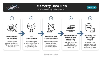
How Telemetry Data Flows: From Test Article to Ground Station
Understanding the data path end-to-end helps engineers identify where problems originate when something goes wrong.
Measurement and encoding: Sensors sample physical phenomena at defined intervals. Signal conditioners normalize the outputs, and the PCM encoder assembles all channels into a structured frame — sync pattern, frame rate, and word length defined — per IRIG 106 Chapter 4.
RF transmission: The transmitter modulates the data stream onto the RF carrier. Before flight, engineers run a link budget accounting for transmitter power, antenna gain, path loss, and receiver noise figure to confirm adequate signal margin across the full flight envelope.
Reception and signal recovery: The tracking antenna follows the aircraft and feeds the signal through the LNA and receiver. The receiver demodulates and extracts the baseband PCM stream; the bit synchronizer then locks to the recovered digital clock.
Decommutation and real-time processing: The decommutator separates the multiplexed stream into individual parameters, applies calibration, and delivers engineering unit values to displays and safety monitoring systems.
Archiving and post-flight analysis: All data is time-stamped and stored in IRIG 106 Chapter 10 format. Engineers replay the flight, cross-reference parameters, and flag any dropouts or anomalies from the mission.
Telemetry Integration: Connecting Components Into a Working System
Selecting components is only half the work. Integration — verifying that every airborne and ground element is compatible and functions correctly end-to-end — is where programs lose schedule.
What Integration Actually Covers
- RF link budget validation — confirming adequate margin at maximum range and worst-case flight attitude
- Data format compatibility — PCM frame structure, word lengths, and encoding must match between the onboard encoder and the ground decommutator
- Timing synchronization — multi-site ground stations receiving the same aircraft must share a common time reference (IRIG A/B/G or IEEE 1588 PTP)
- IRIG 106 compliance — ensures interoperability across different vendors, ranges, and contractors
The Modular Platform Advantage
Firmware-configurable platforms have changed how integration is approached. Rather than deploying separate boxes for receiver, bit synchronizer, decommutator, and combiner, a single hardware unit performs multiple functions through firmware personalities. This reduces rack space, simplifies cabling, and allows field reconfiguration as test requirements change.
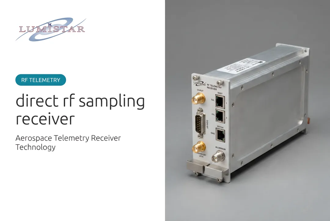
Lumistar's LS-28-DRSM series, introduced in 2017, exemplifies this approach. A single hardware module — roughly 6" × 4" × 1.67" and under 1 kg — can be configured as a multi-band receiver, dual-channel bit synchronizer, decommutator, diversity combiner, or all simultaneously. It covers 200 MHz to 6 GHz, supports PCM/FM, SOQPSK-TG, ARTM CPM, and a dozen other modulation formats, and outputs IRIG Chapter 10 UDP packets directly over Gigabit Ethernet.
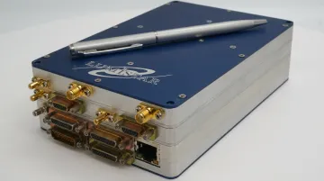
Lumistar's product line spans from RF reception through bit synchronization, decommutation, data display (LDPS software), and Chapter 10 archiving — covering the full ground station stack from a single supplier, which reduces procurement complexity and vendor coordination overhead.
Common Integration Challenges
- Antenna placement and RF interference on the test article, particularly near control surfaces or fuselage discontinuities
- Link margin for long-range or high-speed tests where path loss is higher than a standard range scenario
- Multi-site synchronization when two or more ground stations must track the same aircraft and their data streams need time-correlation
- Data latency — safety monitoring systems need parameters fast enough for real-time decisions, which drives architecture choices in the decommutation and display pipeline
Telemetry Applications in Aerospace and Defense
Flight Test: Manned Aircraft and Prototypes
Airframe manufacturers and defense contractors instrument prototype aircraft to capture aerodynamic loads, structural strains, flight control positions, engine parameters, and hundreds of other channels during envelope expansion. Real-time telemetry gives the ground team the same situational awareness as the pilot, which is essential when pushing the vehicle to the edges of its flight envelope.
Missiles and UAVs
Missiles and UAVs carry no onboard operators, making telemetry the only real-time window into vehicle performance and health. High-speed, high-maneuverability platforms create additional design demands: antenna coverage must account for extreme attitude variations, and the link budget must hold at high closing velocities.
Range safety officers rely on live telemetry to execute flight termination if a vehicle deviates from its planned corridor.
Federal Test Ranges
U.S. government test ranges — operated by the Air Force, Navy, and Army — run multi-site ground station networks covering large geographic areas. The Edwards AFB 5790 Telemetry Site supports the ground portion of telemetry missions and relays aircraft data in real time for the 412th Range Squadron.
All test articles operating at these ranges must meet the following baseline requirements:
- Comply with IRIG 106 telemetry standards (Class I or Class II)
- Coordinate frequency use through AFTRCC (the Aerospace Frequency Technical Review Coordinating Committee)
- Operate within assigned frequency bands to avoid interference across range sites
Frequently Asked Questions
What are the components of telemetry?
Core hardware components split between two subsystems: airborne (sensors, signal conditioners, PCM encoder, RF transmitter, onboard antenna) and ground (receiving antenna, RF receiver/LNA, bit synchronizer, frame synchronizer, decommutator, data display, and archiving system). Both subsystems must be matched and calibrated to function as a complete end-to-end link.
What are the different types of telemetry systems?
PCM/FM is the primary standard in aeronautical flight test per IRIG 106, dominant since around 1970. Bandwidth-efficient variants like SOQPSK-TG and ARTM CPM address spectrum constraints at higher data rates. IP-based networked telemetry (TmNS, IRIG Chapter 26) extends this further by distributing data across multiple ground sites over standard Ethernet.
What is telemetry integration?
The process of selecting, configuring, and verifying that all airborne and ground components function together as a complete, interoperable system. It covers RF link budget validation, PCM data format compatibility, timing synchronization across ground sites, and IRIG 106 compliance.
What is an example of a telemetry system?
A prototype aircraft fitted with pressure and strain sensors feeding a PCM encoder and S-band RF transmitter through a blade antenna. On the ground: a tracking dish antenna feeds an RF receiver and LNA, followed by a bit synchronizer, decommutator, and engineering workstations displaying live parameter values to the test team in real time.
What is included in telemetry data?
Aeronautical telemetry data covers pressures, temperatures, accelerations, structural strains, control surface positions, engine parameters, and avionics bus data. All parameters are time-stamped and multiplexed into a PCM frame per IRIG 106 Chapter 4, then transmitted continuously for real-time monitoring and post-flight analysis.