Without telemetry, ground engineers cannot see what a vehicle is experiencing during a high-stress maneuver. They cannot verify engine health, monitor structural loads, or make a range safety call before something goes wrong. The global aerospace testing market sits at $5.29 billion in 2024 and is projected to reach $6.68 billion by 2029 — a figure that reflects how deeply test programs depend on the data infrastructure that telemetry provides.
Despite being standard equipment across military, federal range, and commercial flight test programs, how telemetry actually works — from sensor excitation through RF transmission to ground-side processing — is frequently misunderstood. That gap leads to mismatched system components, compliance oversights, and avoidable data quality problems. This guide covers the full signal chain in practical terms.
Key Takeaways
- Real-time vehicle telemetry collects sensor data onboard a moving vehicle and transmits it via RF link to a ground station for immediate processing and display
- The system operates in four stages: sensor collection → PCM encoding and RF transmission → ground station reception and demodulation → data processing and display
- Parameters measured include engine performance, structural loads, aerodynamic forces, GPS position, fuel state, and avionics health
- Telemetry enables real-time range safety decisions and vehicle health monitoring that onboard recorders alone cannot provide
- IRIG 106-24 (Range Commanders Council, October 2024) governs aeronautical telemetry interoperability across test ranges
What Is Real-Time Vehicle Telemetry?
Real-time vehicle telemetry is the automated collection of measurement data from sensors distributed throughout a moving vehicle and its transmission via RF or wireless link to a remote receiving station, where it is processed and displayed as events happen — not after the vehicle lands.
Post-flight data download retrieves recorded data after recovery. Onboard data logging captures a complete record but cannot influence the mission in progress. Telemetry is different: it puts live vehicle state information in front of engineers while the test is still running.
What Problem Does It Solve?
During a high-speed maneuver or an envelope-expansion test point, nobody can see inside the airframe. Telemetry provides that visibility. According to Edwards Air Force Base, engineers monitoring the real-time stream at Ridley Mission Control Center can call "knock it off" the moment engine data or control-surface readings indicate a hazardous condition. That call cannot happen if the data only becomes available after landing.
What Telemetry Is Not
A common source of confusion is conflating telemetry with simpler data systems:
- GPS tracking reports position only — not what the vehicle is physically experiencing
- OBD-II diagnostics retrieve stored fault codes after the fact, not live engineering data
- Onboard flight data recorders capture a complete record but cannot close the loop with ground engineers during the mission
Telemetry delivers a continuous, live data stream. The communication link may run vehicle-to-ground only, but it enables real operational decisions: engineers on the ground can evaluate what they see and intervene before something goes wrong.
System Configurations
Two ends must work together for telemetry to function:
- Onboard system — sensors, signal conditioning, PCM encoder, RF transmitter, and antenna installed on the test vehicle
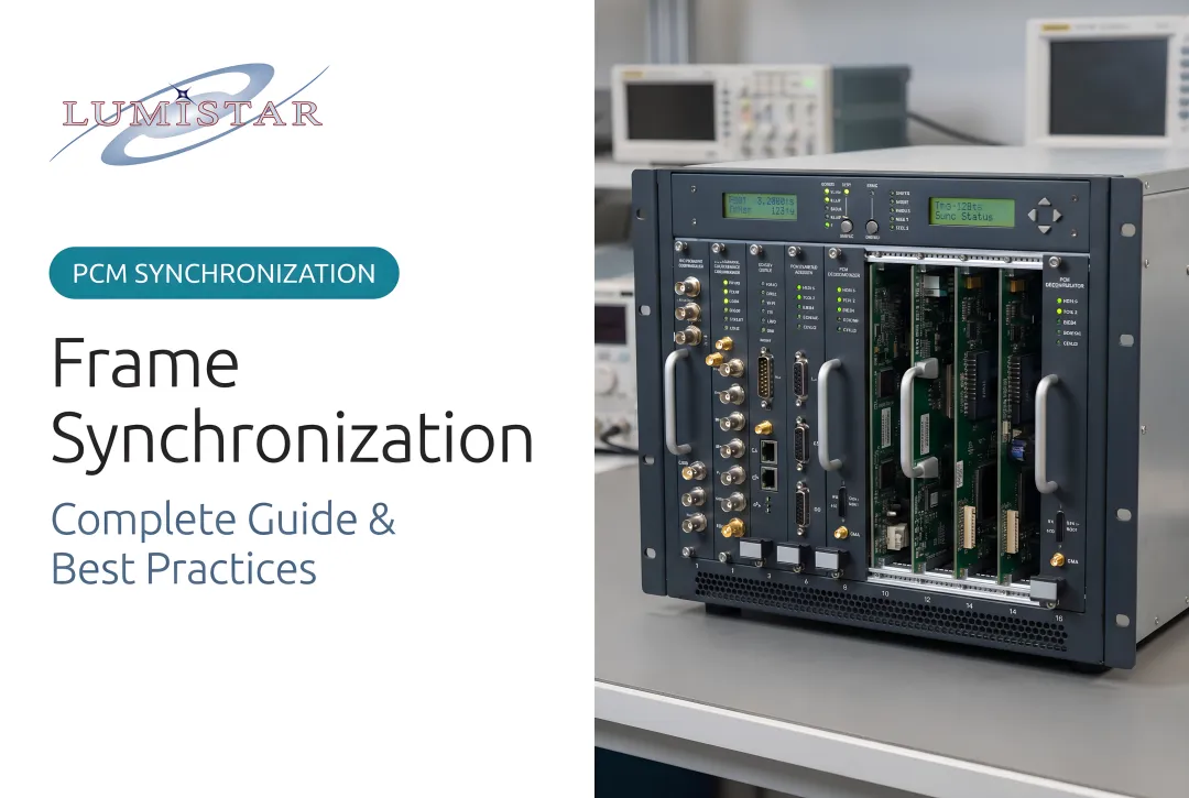
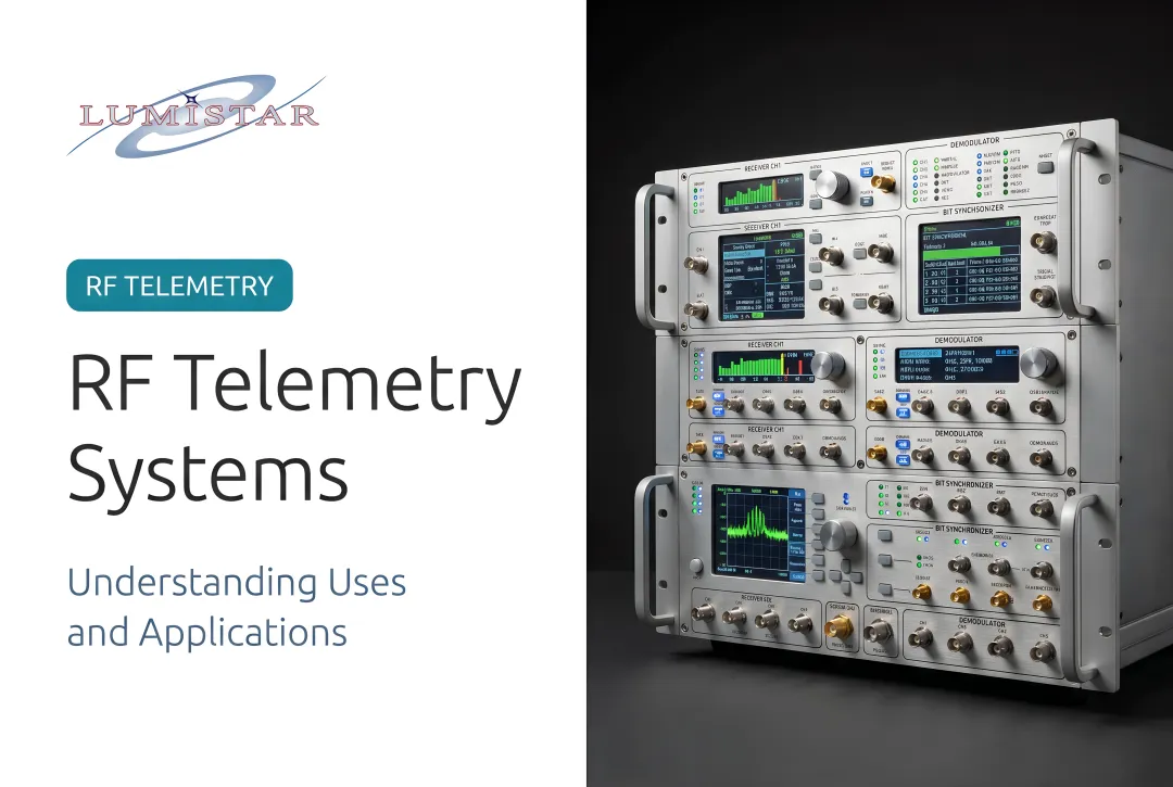
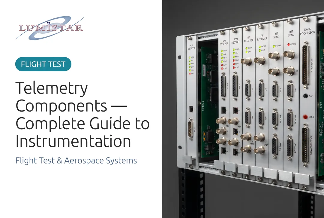
- Ground telemetry receiving station — tracking antenna, receiver/demodulator, bit synchronizer, decommutator, and data display software
Both ends must comply with the same standard — IRIG 106 for aeronautical applications — for the data stream to be interpretable. Architectures vary based on program scope:
- Point-to-point links — single vehicle, dedicated flight test environment
- Multi-vehicle tracking systems — federal ranges managing several test assets simultaneously
- Relay configurations — an airborne platform retransmits data from a vehicle beyond line-of-sight
How Does Real-Time Vehicle Telemetry Work?
Telemetry operates through four sequential stages. A failure or degradation at any stage affects what engineers see at the output.
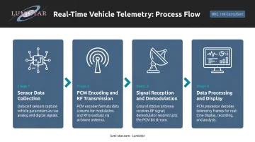
Stage 1: Sensor Data Collection
The process starts with physical transducers distributed across the test vehicle. Common sensor types include:
- Accelerometers and gyros for inertial measurements and angular rates
- Strain gauges and pressure transducers capturing structural loads and aerodynamic pressures
- Thermocouples monitoring engine and thermal performance
- Fuel flow meters tracking propulsion system output
- GPS receivers providing real-time position and velocity
- Avionics bus taps (MIL-STD-1553) pulling digital data from onboard systems
AGARD's flight test instrumentation reference notes that modern flight test systems may record one to two thousand parameters — a scale that reflects how comprehensively complex test articles must be instrumented.
Most aeronautical telemetry uses continuous sampling at fixed rates, not event-triggered capture. Transient events during maneuvers happen fast; a sampling gap means lost data. Sensor placement, sample rate, and signal conditioning are engineering decisions made during instrumentation planning — and they directly determine data quality at every downstream stage.
Stage 2: PCM Encoding and RF Transmission
Raw sensor signals route to a Pulse Code Modulation (PCM) encoder, which digitizes and multiplexes them, combining multiple channels into a single formatted bit stream. IRIG 106 Chapter 4 defines the PCM pulse train structure and system design characteristics that govern this formatting. Class I PCM handles standard applications; Class II supports higher-complexity requirements including bit rates above 10 Mbps.
The formatted bit stream then hands off to the RF transmitter, which modulates it onto a carrier frequency and broadcasts via the onboard antenna. Verified IRIG 106 frequency bands include:
| Band | Frequency Range |
|---|---|
| Lower L-band | 1435–1525 MHz |
| Lower S-band | 2200–2290 MHz |
Transmitter power, antenna placement, and frequency selection are determined during pre-test planning to ensure adequate link margin throughout the vehicle's expected flight envelope. The antenna pattern must provide ground coverage through all planned attitudes and maneuver regimes, not just straight-and-level flight.
Stage 3: Signal Reception and Demodulation
On the ground, a directional tracking antenna follows the vehicle and captures the transmitted signal. At Edwards AFB, the 5790 Telemetry Site performs exactly this function — antennas track the aircraft and relay mission data to Ridley Mission Control Center within seconds. At Eglin's Gulf Test Range, the facility can collect telemetry from aircraft up to 100 miles offshore using remote antenna and receiver control.
The received signal passes through a low-noise amplifier and into a receiver/demodulator, which extracts the PCM bit stream from the RF carrier. This stage is where signal quality problems surface most visibly: multipath interference, off-axis antenna angles, and atmospheric effects all raise bit error rates.
Diversity combining — using two antennas or two sites — is the standard technique for maintaining data integrity through fading events. Lumistar's LS-28-DRSM series supports Pre-D (pre-detection) combining with a break frequency exceeding 50 kHz, handling rapid signal fades up to 30 dB in depth. In Optimal Ratio combining mode, the system achieves greater than 2.6 dB signal-to-noise improvement — a meaningful margin during the dynamic maneuvering common in envelope expansion testing.
The LS-28-DRSM also reflects how dramatically ground station hardware has evolved:
| Traditional Rack Station | LS-28-DRSM | |
|---|---|---|
| Height | ~8 feet | 1.67 inches |
| Weight | ~250 kg | Under 1 kg |
| Power Draw | Thousands of watts | ~40–50 watts |
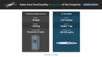
Equivalent core reception functionality, in a fraction of the footprint.
Stage 4: Data Processing and Display
The clean bit stream feeds into decommutation software, which separates the multiplexed channels back into individual parameters, applies calibration coefficients to convert raw digital counts into engineering units, and routes the result to display workstations and archives — all within milliseconds of the event occurring on the vehicle.
At the workstation level, that translates to:
- Real-time strip charts and digital displays showing vehicle health parameters
- Range safety monitors watching structural load and control surface data for abort criteria
- Simultaneous data archiving for post-flight analysis and report generation
The White Sands Missile Range flight safety workflow illustrates this directly: safety personnel continuously monitor real-time vehicle position and telemetered performance parameters — fin positions, motor chamber pressure, FTS status — to determine if a vehicle may leave range boundaries or endanger personnel.
Lumistar's LDPS (Lumistar Data Processing Software) handles real-time display and processing at this stage. It integrates with hardware platforms including the LS-28-DRSM-P1 portable ground station and supports client-server architecture for distributed telemetry operations across multiple workstations.
What Does Real-Time Vehicle Telemetry Measure?
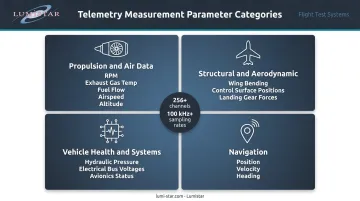
Every flight test program begins with an instrumentation plan — a prioritized list of what to measure, constrained by available telemetry bandwidth. Parameters typically fall into four categories:
Propulsion and air data:
- Engine RPM, exhaust gas temperature, fuel flow, and thrust estimates
- Airspeed, altitude, and angle of attack from pitot-static and air data systems
Structural and aerodynamic:
- Wing bending moments and fuselage stress via strain gauges
- Control surface positions and hinge moments
- Landing gear status and deployment forces
Vehicle health and systems:
- Hydraulic pressure, electrical bus voltages, fuel quantity and balance
- Avionics system status, environmental control data
- For missile test programs, White Sands data indicates over 50 real-time safety parameters may be required — including FTS battery voltage, motor arming status, and receiver AGC voltage
Navigation:
- GPS position, velocity, and heading for range boundary monitoring and post-flight trajectory reconstruction
Today's PCM systems and networked telemetry architectures routinely handle 256 or more channels at sampling rates above 100 kHz — enough to capture high-frequency structural dynamics and fuel slosh in real time, which older hardware simply couldn't do.
Where Real-Time Vehicle Telemetry Is Used
Real-time vehicle telemetry is used across aeronautical and aerospace flight test programs — from civil certification campaigns to military test ranges. Within each program, it follows a consistent operational workflow:
- Pre-flight — ground run or bench test verifies all channels are live and calibrated; simulators like Lumistar's LS-18-P1 generate known PCM data streams to confirm ground station reception end-to-end
- In-flight — engineers monitor the real-time stream to verify test point conditions and vehicle health; range safety officers watch structural and control data for abort criteria
- Post-flight — archived telemetry data serves as the primary record for performance analysis, safety review, and certification reporting
The specific hardware requirements shift depending on the platform being tested:
- Fixed-wing aircraft — traditional RF ground station setups with directional tracking antennas; programs span military services, defense contractors, and civil certification
- UAVs — integrated command-and-telemetry links; limited onboard storage on small UAS platforms increases dependence on real-time downlink
- Missiles and expendable vehicles — reliable one-way downlink prioritized over short mission durations; range safety telemetry is required for range safety compliance
- Rockets and launch vehicles — high dynamic environments and rapidly changing altitude significantly affect RF link geometry
Lumistar's products serve this community across all these categories — from portable lunchbox ground stations used by commercial flight test operators to rack-mounted systems deployed at federal test ranges supporting missile and aircraft programs.
Conclusion
Real-time vehicle telemetry is an active engineering tool, not a passive monitoring feed. It closes the information loop between a vehicle in flight and the engineers responsible for its safety and mission outcome. Understanding each stage of the signal chain — from sensor selection and PCM formatting through RF transmission, reception, and ground-side processing — is what allows programs to select matched system components, design effective instrumentation plans, and troubleshoot data quality problems before they affect mission results.
Programs that treat telemetry hardware as interchangeable commodity equipment take on real, measurable risks:
- Compliance gaps when components don't meet IRIG 106 or range requirements
- Degraded link performance from mismatched RF characteristics across the signal chain
- Unusable data that can't support the flight test decisions it was collected to inform
Working with specialists who understand the full signal chain — from onboard transmitter characteristics to ground station antenna diversity — reduces that exposure and keeps your data reliable when it matters most.
Frequently Asked Questions
What is real-time vehicle telemetry?
Real-time vehicle telemetry is the process of collecting data from onboard sensors, encoding and transmitting it via RF link, and processing it at a ground station so engineers can monitor vehicle performance as events occur — not after recovery or data download. This gives flight test teams immediate visibility into what the vehicle is physically experiencing throughout the mission.
What data does real-time vehicle telemetry collect?
Common parameters include engine and propulsion data, structural loads measured via strain gauges, aerodynamic and flight dynamics data, GPS position and velocity, avionics system health, and test-article-specific measurements defined during instrumentation planning. Complex programs may instrument hundreds of channels simultaneously.
How does telemetry data get transmitted from a moving vehicle to a ground station?
The transmission chain follows three stages:
- Onboard sensors feed a PCM encoder that digitizes and multiplexes the data into a formatted bit stream.
- An RF transmitter broadcasts that stream on a designated frequency band — typically L-band or S-band for aeronautical applications.
- A directional ground station antenna tracks the vehicle and passes the captured signal to a receiver/demodulator for processing.
What is IRIG 106 and why does it matter for aeronautical telemetry?
IRIG 106 is the Telemetry Standard issued by the Range Commanders Council's Telemetry Group (currently IRIG 106-24, October 2024). It defines how telemetry data must be formatted, transmitted, and received — ensuring hardware from different vendors and programs can exchange data without compatibility issues at federal test ranges.
What is the difference between GPS tracking and real-time vehicle telemetry?
GPS tracking reports only location. Telemetry captures the full internal state of the vehicle — engine parameters, structural loads, system health, control surface positions, and more. Engineers need to know not just where the vehicle is, but what it is physically and mechanically experiencing throughout the test mission.
What are the most common challenges in real-time vehicle telemetry systems?
The most common challenges include:
- Maintaining RF link margin across the full flight envelope and maneuver range
- Bandwidth limitations that constrain how many channels can be transmitted simultaneously
- Antenna tracking accuracy during high-dynamic maneuvers
- Multipath interference in low-altitude or over-water flight
- Ensuring IRIG 106 compliance across all components, from onboard transmitter to ground station software