The challenge is that TT&C gets treated as a single concept when it's actually three distinct subsystems — each with its own signal direction, hardware chain, and operational requirements. Teams that conflate them tend to design incomplete ground stations, miss range compliance requirements, or lose test data at the worst possible moment.
This article breaks down how each component works, how they interconnect end-to-end, and where the common points of confusion create real operational risk.
Key Takeaways
- TT&C = Telemetry + Tracking + Command — three interdependent subsystems that must function together
- Telemetry is the downlink of vehicle health and performance data to the ground
- Tracking is the continuous determination of vehicle position to maintain antenna lock and RF link margin
- Command is the uplink of verified operational instructions from ground to vehicle
- At federal test ranges, TT&C — including flight termination — must comply with RCC Document 319-25 and range safety rules
- Treating "telemetry" as synonymous with "TT&C" creates system design gaps that compromise both safety and test validity
What Is a TT&C System?
A TT&C system is a networked architecture of ground-based and vehicle-based hardware that supports bidirectional communication between operators and a test vehicle or spacecraft.
The three things it must deliver simultaneously:
- Continuous vehicle status visibility — health, performance, and sensor data transmitted to the ground in real time (telemetry)
- Precise vehicle location — position and trajectory data used to maintain antenna pointing and RF link integrity (tracking)
- Verified command execution — uplink instructions that the vehicle receives, acknowledges, and acts on (command)
TT&C vs. Related Systems
A common source of confusion is the boundary between TT&C and payload data transmission (PDT). PDT carries mission or science data — imagery, radar returns, experimental measurements. TT&C carries vehicle health, position, and control data. The distinction matters because they often use separate RF links, different frequency allocations, and independent ground processing chains.
Treating "telemetry" as shorthand for the entire TT&C system is a persistent error. Telemetry is one subsystem — the downlink data stream. TT&C also includes the tracking function that keeps the antenna pointed at the vehicle, and the command uplink that lets operators send instructions. A ground station configured for telemetry reception only is missing two-thirds of the architecture.
The Three Components of TT&C
Each component has a distinct signal direction, data type, and hardware dependency. Gaps in any one of them compromise the whole system.
Telemetry
Telemetry is the process of collecting onboard sensor data — temperature, voltage, pressure, attitude, structural loads, fuel state — encoding it digitally, and transmitting it via RF downlink to the ground station.
In flight test, telemetry output is the primary record of vehicle performance against test objectives. Losing the telemetry stream mid-flight doesn't just mean missing data — it often means the test can't be validated and must be re-flown.
The standard governing US aeronautical flight test telemetry is IRIG Standard 106-24R1, published by the Range Commanders Council. IRIG 106 Chapter 2 covers PCM/FM as the traditional modulation method, along with bandwidth-efficient alternatives including SOQPSK-TG, FQPSK variants, and ARTM CPM. Data is formatted as PCM (Pulse Code Modulation), transmitted via RF, received by the ground antenna, demodulated, decoded, and fed into display and archiving systems.
Lumistar's ground telemetry equipment supports IRIG 106 Class I and II compliance across a full range of PCM codes — NRZ-L/M/S, Bi-Phase, Differential Manchester, and randomized codes — along with virtually any custom data format, making them suitable for both standard federal range configurations and custom flight test programs.
Tracking
Tracking is the continuous determination of a vehicle's position, velocity, and trajectory during flight. Its primary function in the ground station context is keeping the directional antenna locked onto the vehicle — without tracking, the antenna drifts off-axis, RF link margin collapses, and the telemetry stream degrades or drops entirely.
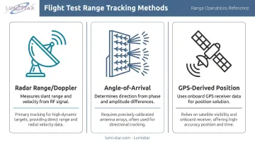
Common tracking methods in flight test range operations include:
- Radar range/Doppler — measures slant range and velocity directly from the RF signal
- Angle-of-arrival — determines vehicle direction from signal phase or amplitude differences across antenna elements
- GPS-derived position — uses position data from the vehicle's onboard GPS receiver
Many ground stations use the telemetry antenna itself for tracking, with AGC (Automatic Gain Control) and AM outputs from the receiver feeding the antenna pedestal's positioning system.
Lumistar's LS-27-M Series tracking receivers are specifically designed for auto-tracking antenna systems, generating programmable AGC and AM signals for antenna control. The LS-28-DRSM Series includes an independent dual-channel antenna tracking receiver function with user-programmable AGC outputs — designed for direct integration into tracking antenna pedestals.
A GPS position packet embedded in the telemetry stream is not the same thing as the tracking subsystem. The embedded GPS data tells you where the vehicle is. The tracking function tells the antenna where to point. These are operationally distinct — treating them as equivalent can leave antenna control gaps even when position data looks correct.
Command
The command subsystem is the uplink channel — signals travel from the ground to the vehicle, the opposite direction from telemetry. Ground operators use it to transmit instructions ranging from routine mode changes and instrument activation to safety-critical actions including flight termination.
Command verification is an essential step in this process. Commands are encoded, transmitted, received by the onboard transponder, and echoed back to the ground for confirmation before execution — preventing erroneous command execution from a corrupted or misinterpreted signal.
At test ranges where range safety requirements apply, flight termination systems (FTS) represent the most critical command function. RCC Document 319-25, "Flight Termination Systems Commonality Standard," governs FTS design, testing, and commonality requirements at US ranges. Range-specific implementation guides — such as the one published by Vandenberg Space Force Base for SLD 30 — apply these requirements to individual range operations.
Lumistar's product line covers the telemetry downlink and tracking segments. Command uplink hardware requires sourcing from specialized vendors — identifying this boundary early in ground station design prevents scope gaps that are expensive to close later.
How a TT&C System Works End-to-End
The three subsystems run concurrently during a test mission. Here's the full signal chain:
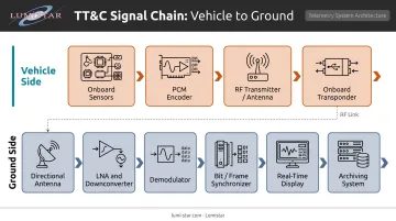
Vehicle side: Onboard sensors generate data → PCM encoder formats it → RF transmitter broadcasts the downlink signal → onboard transponder receives command uplink
Ground side: Directional antenna captures the RF signal → LNA and downconverter handle front-end processing → demodulator reconstructs the baseband signal → bit synchronizer and frame synchronizer recover data structure → real-time display presents data to test engineers → archiving systems record for post-flight analysis
Tracking runs in parallel throughout, keeping the antenna locked on the vehicle. The command channel operates simultaneously on a separate uplink frequency.
Each stage in that chain maps to specific hardware — both on the ground and aboard the vehicle. Here's how those segments break down.
The Ground Segment
A TT&C ground station includes:
- Tracking antennas — pedestal-mounted, auto-track capable
- RF front end — LNA, downconverter, band-switching for L-band and S-band
- Demodulators — multi-mode, supporting PCM/FM, SOQPSK, BPSK, QPSK, and others
- Bit synchronizers and frame synchronizers — recover clock, data, and frame structure from the demodulated signal
- Real-time display software — presents decommutated parameters to flight test engineers
- Data recorders — archive both raw RF and processed data for post-flight analysis
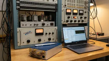
Lumistar's ground telemetry product line covers each stage of this chain, from RF reception through data display and archiving, built to IRIG 106 standards. The LS-28-DRSM Series packs a complete dual-channel ground station into a single enclosure: receiver, diversity combiner, 64 GB data recorder per channel, TMoIP Ethernet streaming, and telemetry processing — measuring just 6.00" × 4.00" × 1.67" and weighing 0.84 kg.
For context on what that represents: equivalent ground station capability once required an 8-foot rack weighing 250 kg and consuming several thousand watts. The modular approach means customers can configure a complete ground station from a single vendor rather than sourcing hardware from multiple manufacturers.
The Airborne Segment
Vehicle-side hardware must survive the flight environment while remaining compact and low-power. The airborne TT&C segment typically includes:
- PCM encoder aggregating sensor data
- RF transmitter and antenna for telemetry downlink
- Transponder and receiver for command uplink (where required)
Lumistar's LS-28-DRSM is also rated for airborne deployment — the same core hardware used in ground stations can be configured for chase plane reception or airborne re-transmission, operating on +9 to +42 VDC and consuming approximately 40 watts.
Signal Flow During a Test Mission
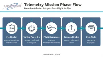
- Pre-mission — antenna boresighting, link budget verification, telemetry stream acquisition check
- Vehicle power-on — telemetry stream confirmed at ground station, tracking lock established
- Flight operations — live data displayed and recorded; tracking continuously maintains antenna lock
- Command uplink — instructions transmitted, echoed back, verified, executed
- Post-flight — mission data archived; RF recordings available for playback and re-analysis
All three subsystems must be operational simultaneously for a valid test. Losing any one of them mid-mission creates either a data gap, an antenna dropout, or loss of vehicle control capability.
Where TT&C Systems Are Applied
TT&C requirements vary significantly across operational environments:
| Environment | Primary TT&C Requirements |
|---|---|
| Aeronautical flight test ranges | IRIG 106 compliance, real-time telemetry, range safety command |
| Missile and munitions testing | High-rate telemetry, FTS mandatory where range safety requires |
| UAV/UAS operations | Often lower-bandwidth telemetry; command link is operationally critical |
| Satellite/spacecraft operations | S-band, X-band TT&C; different regulatory framework |
Edwards AFB's 5790 Telemetry Site illustrates what operational ground telemetry infrastructure looks like in practice — supporting aircraft missions by relaying test data from flight test vehicles across the range network. NASA Dryden Flight Research Center at Edwards similarly served as responsible range authority for extended test range operations, including the X-33 program.
TT&C coverage must hold across the entire test program lifecycle — from ground checkout and early envelope testing through envelope expansion and long-duration operational missions. At federally controlled ranges, real-time telemetry and flight termination command capability are mandated range safety requirements, not discretionary choices.
Lumistar's systems support this operational reality across federal test ranges and commercial flight test programs wherever IRIG 106-compliant telemetry reception is required — in fixed ground stations, mobile deployments, and airborne relay configurations.
Common Misconceptions About TT&C
"Telemetry and TT&C are the same thing." Telemetry is the downlink data stream — one subsystem. TT&C is the complete bidirectional architecture. Teams that configure telemetry reception without addressing tracking and command uplink lack the infrastructure needed for controlled flight test operations and range safety compliance.
"Tracking means GPS." GPS position data embedded in the telemetry stream tells you where the vehicle is. The tracking subsystem is what keeps the antenna pointed at it. These serve different functions: one is a data parameter, the other is an RF link management function. A vehicle can transmit GPS coordinates perfectly while the ground antenna loses lock if the tracking subsystem isn't properly configured.
"TT&C systems are fixed ground installations." Modern flight test telemetry systems are increasingly mobile. Lumistar's LS-28-DRSM delivers full ground station capability (receiver, combiner, recorder, and telemetry processing) in a 0.84 kg unit deployable in mobile vehicles, on antenna pedestals, or in airborne relay configurations.
The shift from 250 kg rack systems to sub-1 kg portable units reflects both defense program requirements for expeditionary test ranges and commercial flight test demands for flexible, deployable infrastructure.
Here's how those three misconceptions compare at a glance:
| Misconception | What It Misses |
|---|---|
| Telemetry = TT&C | TT&C also includes tracking and command uplink |
| Tracking = GPS | GPS is a data parameter; tracking manages the RF link |
| TT&C = fixed ground station | Modern units under 1 kg support fully mobile deployment |
Frequently Asked Questions
What is telemetry tracking and command?
TT&C is the integrated communication architecture used in aerospace and flight test to receive vehicle health data (telemetry), determine vehicle position (tracking), and send verified operational instructions to the vehicle (command). It functions as the primary link between ground operators and the vehicle throughout a mission.
What is a TT&C station?
A TT&C station is the ground-based infrastructure — antennas, RF receivers, signal processing hardware, and command uplink equipment — that manages all three TT&C functions for one or more vehicles. Modern stations range from fixed multi-rack installations to portable single-enclosure systems.
What frequency bands are used in TT&C systems?
Per IRIG 106, aeronautical mobile telemetry allocations include lower L-band (1435–1535 MHz), lower S-band (2200–2290 MHz), and an upper S-band segment around 2310–2390/2395 MHz. The NTIA Manual governs federal spectrum use; IRIG 106 governs test-range implementation.
What is the difference between uplink and downlink in a TT&C system?
Downlink refers to signals transmitted from the vehicle to the ground — telemetry data and tracking returns. Uplink refers to signals transmitted from the ground to the vehicle — command instructions. Full TT&C operation requires both links active; losing either degrades mission control or safety response capability.
What standard governs flight test telemetry in the US?
IRIG Standard 106 — published by the Range Commanders Council's Inter-Range Instrumentation Group — is the governing standard. It covers data formats, frequency allocations, modulation methods, and equipment requirements for aeronautical and range telemetry. The current revision is 106-24R1.
Can a TT&C system operate without all three components active?
Yes, but with significant risk. Telemetry-only operation enables monitoring while removing the ability to correct vehicle behavior or execute safety actions. Loss of tracking degrades antenna pointing and can break the telemetry link entirely — making partial TT&C an unsafe posture at ranges where command capability is a safety requirement.