Introduction
Every parameter measured during a flight test — airspeed, structural load, fuel state, engine temperature — depends on one thing arriving intact at the ground station: the PCM data stream.
Defined in IRIG 106 Chapter 4, a PCM data stream is a continuous serial binary output that combines digitized measurements from multiple onboard sensors into a single transmission-ready sequence using Time Division Multiplexing (TDM).
For flight test engineers, FTI system integrators, ground station operators, and defense range personnel, getting this stream right is non-negotiable. A corrupted word at the wrong moment means a missed test point — and in flight test, missed test points often can't be repeated.
This guide covers how a PCM stream is constructed onboard, how it travels to and gets decoded at the ground station, what degrades it, and where teams most often go wrong.
Key Takeaways
- PCM data streams are serialized binary sequences from a DAU, multiplexing multiple sensor channels via Time Division Multiplexing
- IRIG 106 Chapter 4 sets the standard: frame structure, sync patterns, bit representations, and bit rate rules
- Embedded Frame Sync patterns let ground equipment locate frame boundaries and extract per-channel data
- Match three parameters to your measurement requirements: bit rate, bit depth, and sample rate
- Processing sequence runs: RF receiver → bit synchronizer → frame synchronizer → decommutator → engineering unit output
What Is a PCM Data Stream?
In flight test instrumentation, a PCM data stream is a continuous, serialized binary output. Each sensor measurement converts to a binary word, multiple words assemble into repeating frames, and the entire sequence transmits as a single serial bit stream from the test article to the ground station.
Unlike consumer PCM audio, a telemetry PCM stream carries multi-channel measurement data across dozens or hundreds of parameters simultaneously. It must comply with IRIG 106 Chapter 4 formatting standards and is transmitted over RF links using PCM/FM modulation — not delivered over HDMI or S/PDIF.
One property that surprises engineers new to the field: word slots in the stream carry no channel labels. The stream is attributeless. Channel identity is determined by word position within the frame structure, which is why a correctly defined frame structure and a matching TMATS configuration file are prerequisites for any useful output.
That positional dependency makes two stream characteristics non-negotiable:
- Bit rate — the number of bits transmitted per second, governing total stream throughput
- Frame structure — how channels are organized, identified, and ordered within each repeating frame
How a PCM Data Stream Is Constructed
A PCM data stream doesn't emerge from a single sensor output — it's assembled through a defined sequence of conditioning, digitizing, multiplexing, and framing steps. Understanding each stage clarifies where errors enter the stream and how ground equipment reconstructs usable data from it.
Step 1: Signal Conditioning and Analog-to-Digital Conversion
Each sensor's analog output passes through a Low-Pass Filter (LPF) before reaching the ADC. The LPF removes frequency components above the Nyquist threshold, preventing aliasing from corrupting the digitized result.
The ADC samples the conditioned signal at a defined rate, producing a binary word for each measurement. Two parameters determine output quality:
- Bit depth (word length) — controls amplitude resolution; more bits = finer measurement granularity
- Sample rate — controls time-axis resolution; must be at least twice the highest signal frequency of interest per Nyquist
Per IRIG 106 Chapter 4, the bit rate must not deviate from the nominal specified value by more than 0.1% during any period of desired data. The standard also sets a minimum PCM bit rate of 10 bits per second and classifies streams above 10 Mbps as Class II.
Step 2: Commutation and Time Division Multiplexing
TDM (commutation) assembles binary words from each channel sequentially into a single frame. Three commutation modes handle signals with different update requirements:
- Normal commutation — equal sample rates across all channels; one word per channel per sub-frame
- Sub-commutation — slow-changing signals (fuel level, ambient temperature) occupy a rotating slot appearing only once every N sub-frames within the Major Frame, reducing bandwidth overhead for low-priority channels
- Super-commutation — fast-changing signals (accelerometers, vibration) occupy multiple word slots per sub-frame, increasing their effective sample rate
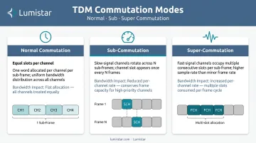
Channel identity depends entirely on position within the frame. There are no inline labels.
Step 3: Frame Sync, SFID, and Bit Representations
Ground equipment needs a reference point to locate frame boundaries. A Frame Sync (FS) pattern (a specific binary sequence chosen for its very low probability of appearing naturally as data) is prepended to each sub-frame.
IRIG 106 Chapter 4 requires minor-frame sync words to be between 16 and 33 consecutive bits. IRIG 106 selected these patterns specifically to minimize false synchronization probability at the ground-station frame synchronizer.
A Sub Frame Identifier (SFID) follows the FS pattern to distinguish sub-frames within a Major Frame, enabling correct reassembly of channels with differing sample rates.
IRIG 106 Chapter 4 defines six permissible binary bit representations:
| Family | Representations |
|---|---|
| NRZ | NRZ-L, NRZ-M, NRZ-S |
| Bi-Phase | Bi-Phase-L, Bi-Phase-M, Bi-Phase-S |
Only one representation is used within a single PCM stream. Once the bit representation is selected, the stream is ready for modulation. PCM/FM (the IRIG 106 standard modulation scheme) carries the stream to the ground station across designated IRIG telemetry sub-bands:
| Band | Sub-band Frequencies |
|---|---|
| Lower L-band | 1435–1525 MHz |
| Lower S-band | 2200–2290 MHz |
| Upper S-band | 2310–2395 MHz |
| Lower C-band | 4400–4940 MHz |
| Middle C-band | 5091–5150 MHz |
| Upper C-band | 5925–6700 MHz |
Receiving and Decoding PCM Data Streams at the Ground Station
RF Reception and Bit Synchronization
A tracking antenna captures the RF signal from the airborne transmitter and routes it to the telemetry control room. The RF receiver extracts a raw, unsynchronized bit stream from the carrier.
In well-equipped stations, the raw RF signal is recorded before any conversion. Lumistar's LS-29-R2 Series RF Recording & Playback System supports two or four channels with up to 50 MHz instantaneous bandwidth per channel, stores data in VITA 49 format, and provides a reprocessing backup if downstream issues arise.
The Bit Synchronizer locks onto the recovered signal to reconstruct a clean PCM data stream while generating a synchronized clock pulse matching the original data rate. Performance is expressed as:
- Bit Error Rate (BER) — bit errors per unit time
- Bit Error Ratio — bit errors divided by total bits transferred
IRIG 106-24R1 Appendix 2-A benchmarks PCM/FM performance at approximately 9 dB Eb/N0 for 10⁻⁵ BEP with a multi-symbol detector, versus 12–14 dB for typical FM demodulators with single-symbol detectors. Lumistar's LS-45-R2-HBS bit synchronizer achieves less than 1 dB degradation from theoretical performance for NRZ signals below 20 Mbps.
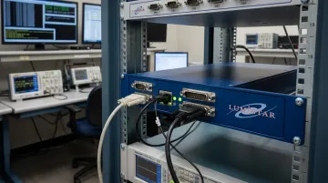
Factors that degrade BER include transmitted signal strength, receiver sensitivity, RF interference, and antenna tracking accuracy. Even minor BER degradation can trigger frame sync failures in the next processing stage — which is why frame synchronizer tolerance settings matter.
Frame Synchronization
The Frame Synchronizer searches the cleaned bit stream for the known FS pattern, tentatively identifies it, then counts bits to verify recurrence before declaring lock. Four configurable tolerances govern this process:
- Search-to-Lock count — consecutive valid FS detections required before declaring lock
- Sync Pattern Bit Errors — acceptable bit mismatches within the FS pattern
- Bit Aperture — acceptable early/late arrival of the FS pattern
- Lock-to-Search threshold — consecutive invalid FS detections before abandoning lock
Lumistar's LS-50-E PCIe Multi-function PCM Decommutator supports sync error tolerance from 0 to 15 bits (selectable) and a sync slip window of 1, 3, 5, or 7 bits. These tolerances must balance sensitivity to genuine sync loss against resilience to temporary BER spikes during antenna handoffs or aircraft maneuvering.
Decommutation and Engineering Unit Output
Once frame lock is established, the decommutator uses a TMATS (Telemetry Attributes Transfer Standard) file (defined in IRIG 106 Chapter 9) to map each word position in the frame to its originating channel, apply calibration scaling, and produce engineering unit output.
Two points are worth keeping in mind for TMATS configuration:
- TMATS attributes support XML expression via an XSD schema, but not all legacy implementations are XML-only
- The TMATS file used in the ground decommutator must match the frame structure defined in the DAU configuration software — any mismatch produces silently incorrect engineering unit values
Lumistar's LS-68 Series Digital Processing Engine covers this entire chain (bit synchronization, frame synchronization, and decommutation) in rack-mount, portable lunchbox, and compact modular configurations, with full IRIG 106 Class I and Class II compliance.
Key Factors That Affect PCM Data Stream Proven Performance
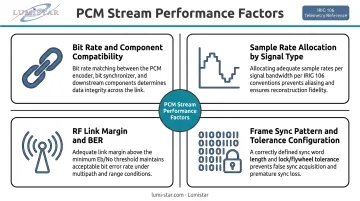
Bit rate and component compatibility: Every component in the chain — DAU, RF transmitter, ground receiver, decommutator — must support the selected bit rate. Lumistar's LS-45-series bit synchronizers handle up to 45 Mbps for NRZ-L and 22.5 Mbps for Bi-Phase/Miller codes, with a minimum of 100 bps. Plan the full chain before locking in a bit rate; discovering hard ceilings during integration is a costly fix.
Sample rate allocation by signal type: Assigning the same sample rate to every channel wastes bandwidth on slow-changing parameters (fuel level, ambient temperature) while under-sampling fast-changing ones (structural vibration, engine parameters). Sub-commutation and super-commutation exist to balance this. Treat sample rate assignment as a deliberate per-channel engineering decision.
RF link margin and BER: Distance, antenna gain, transmitter power, and the RF interference environment all directly influence BER. A well-constructed PCM stream cannot compensate for an inadequate RF link. Characterize BER during pre-test ground checks, not during the test itself.
Frame sync pattern selection and tolerance configuration: Pattern width and sync tolerances are often left at defaults. The IRIG 106 Chapter 4 recommended patterns for 16–30 bits were selected specifically to minimize false sync probability. Configured tolerances must still account for expected operational conditions, including antenna handoffs between tracking dishes and turbulence-induced dropouts.
Common Issues and Misconceptions in PCM Stream Handling
These four mistakes appear consistently across flight test programs — from first-time setups to experienced teams re-using legacy configurations without re-examining the assumptions behind them.
Longer frame sync patterns aren't always better. IRIG 106 limits minor-frame sync words to 16–33 bits, and the recommended patterns in Chapter 4 Appendix A already minimize false sync probability for the typical range of word lengths and channel counts. Extending the pattern beyond what the stream structure requires consumes bandwidth without proportional benefit.
Uniform sample rates across all channels are probably the most common configuration mistake. Teams copy a previous test's setup without revisiting per-channel requirements, which leads to bandwidth exhaustion, oversized data files, and — when a new channel genuinely needs a higher rate — no headroom to add it. Every channel's sample rate should be justified against its signal dynamics.
Momentary frame sync loss isn't always an RF failure. A brief BER spike from an antenna handoff or aircraft maneuver can cause a momentary loss of lock that self-recovers within seconds. Well-configured Lock-to-Search thresholds prevent the system from re-entering full search mode during these recoverable events. Teams that abort based on a sync loss indicator are often responding to a false alarm.
TMATS portability is a pre-test problem, not a test-day discovery. IRIG 106 Chapter 9 defines the standard, but XML structure and attribute interpretation vary between manufacturer implementations. A TMATS file generated by one DAU vendor's configuration software may not map correctly into a different vendor's decommutation software. Validate compatibility across the complete ground chain during pre-test integration, before test day.
Each of these issues shares a common thread: assumptions carried forward from prior programs without validation against the current test's requirements. Checking them early costs minutes; catching them during a test costs the test.
Frequently Asked Questions
What is a PCM stream?
A PCM data stream is a continuous serial sequence of binary data produced by combining digitized sensor measurements from multiple channels via Time Division Multiplexing, structured into repeating frames per IRIG 106 Chapter 4. It is transmitted via RF link from the test article to the ground station, where it is decoded into engineering unit parameters.
What is the difference between bit rate and sample rate in a PCM data stream?
Sample rate is the frequency at which an individual sensor channel is measured (samples per second). Bit rate is the total speed of the entire serialized stream (bits per second), encompassing all channels combined. Total bit rate equals the sum of (sample rate × bit depth) across all channels, plus overhead for frame sync patterns and SFID.
What causes a PCM stream to lose frame synchronization?
An elevated Bit Error Rate is the most common culprit — it prevents the ground frame synchronizer from recognizing the Frame Sync pattern within its configured error tolerance. Common triggers include RF link degradation, antenna handoff, multipath, and RF interference. Re-lock time depends on the configured Search-to-Lock threshold.
What is the difference between sub-commutation and super-commutation?
Sub-commutation places a channel's word in only one out of every N sub-frames, used for slow-changing signals that don't require frequent updates. Super-commutation repeats a channel's word multiple times within a single sub-frame to achieve higher effective sample rates — the standard approach for fast-changing signals like accelerometers.
What is a TMATS file and why is it required to process a PCM data stream?
TMATS (Telemetry Attributes Transfer Standard), defined in IRIG 106 Chapter 9, is a file that tells the decommutator which word position in the PCM frame corresponds to which sensor channel, how to scale the raw binary value, and what engineering units to apply. Without it, the stream is an unidentified sequence of binary numbers with no channel attribution.