Introduction
PCM — Pulse-Code Modulation — is the foundational encoding method behind digital audio, telephony, medical instrumentation, and aerospace telemetry systems. Despite its ubiquity, "PCM data format" means different things depending on context. An audio engineer and a flight test data engineer may both work with PCM daily without realizing they're describing the same underlying mathematics.
That gap in understanding causes real problems. Misconfigured sampling rates produce aliasing. Misidentified bit depths corrupt measurement records. In flight test programs operating under IRIG 106, a single-word offset in a PCM frame map can generate systematically wrong engineering values that look valid until post-flight analysis reveals the error — at which point the data is unrecoverable.
This guide covers the core mechanics of PCM encoding, its defining parameters, its key variants, and how it functions within telemetry systems governed by IRIG Standard 106-24R1. It is written for engineers who specify, configure, and validate data acquisition systems — not as a consumer audio primer.
Key Takeaways
- PCM digitizes analog signals by sampling amplitude at fixed intervals, quantizing each sample to a binary value, and encoding the result as a bit stream.
- Three parameters govern every PCM stream: sampling rate, bit depth, and channel count — together they determine data rate and fidelity.
- PCM is a family of methods: LPCM is uncompressed, while DPCM and ADPCM apply compression with fidelity trade-offs.
- In IRIG 106 telemetry, PCM data is organized into minor and major frames with fixed synchronization words, requiring properly configured decommutation equipment.
- Misapplying parameters (under-sampling, wrong bit depth, misconfigured PCM maps) causes permanent data integrity failures that cannot be corrected post-flight.
What PCM Data Format Represents in Digital Systems
ITU-T G.701 defines PCM as a process in which a signal is sampled, each sample is quantized independently, and the result is converted by encoding into a digital signal. That definition is deliberately domain-agnostic — it applies equally to a voice call, a CD recording, or sensor data streaming from an aircraft.
The encoding process runs in three sequential steps:
- Sampling — The analog signal is measured at a fixed rate. The Nyquist-Shannon theorem requires that rate to be at least twice the highest frequency component in the signal; anything less causes aliasing.
- Quantization — Each measured amplitude is rounded to the nearest level on a finite binary scale, introducing a small but unavoidable residual error.
- Encoding — Quantized values are expressed as binary integers, typically in two's-complement fixed-point format, ready for storage or transmission.
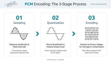
The output is a discrete-time, discrete-amplitude representation of a continuous signal. Its fidelity is determined entirely by the parameters chosen during encoding — sampling rate, bit depth, and clock stability each set a hard ceiling on what can be recovered downstream.
Factors That Influence PCM Data Integrity
Three failure modes account for most PCM data integrity problems in practice. Understanding each one helps in diagnosing issues before they compound during post-flight analysis.
Aliasing occurs when the signal contains frequency components above half the sampling rate. Those components fold back into the valid frequency range and corrupt the encoded data — anti-aliasing filters applied before the ADC are the standard mitigation, because there is no correction possible after the fact.
Quantization error is bounded but never zero. Because amplitude is rounded to a finite scale, every sample carries a small residual. At low bit depths this becomes measurable signal degradation. Dithering can randomize the error distribution, but cannot eliminate the error itself.
Clock stability is the failure mode most likely to surface late in analysis. IRIG 106-24R1 specifies a bit-jitter limit of ±0.1 bit interval referenced to the expected transition time. In high-speed telemetry streams, deviations beyond that threshold disturb the timing relationship between samples — producing systematic reconstruction errors that are difficult to trace back to their source after a flight.
Key PCM Parameters: Sampling Rate, Bit Depth, and Data Rate
Every PCM stream is fully characterized by four quantities: sampling rate, bit depth, channel count, and resulting data rate. Getting any one of them wrong during system specification creates problems that no amount of post-processing can fix.
Sampling Rate
Sampling rate (expressed in Hz) determines the maximum signal frequency that can be faithfully captured. Standard rates by application:
| Application | Sampling Rate | Bit Depth |
|---|---|---|
| Telephony (ITU-T G.711) | 8,000 Hz | 8 bits |
| CD audio | 44,100 Hz | 16 bits |
| Professional audio / DVD | 48,000 Hz | 16–24 bits |
| High-resolution archival | 96,000 Hz+ | 24 bits |
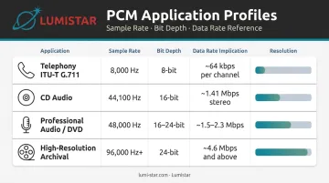
Increasing sampling rate raises data volume proportionally. There is no quality benefit to sampling at 96 kHz if the signal bandwidth is only 20 kHz — it just costs more storage and transmission capacity.
Bit Depth
Bit depth (also called word length or sample resolution) sets the number of discrete amplitude levels available:
- 8-bit: 256 levels — telephony and legacy systems
- 16-bit: 65,536 levels — standard for audio and telemetry
- 24-bit: over 16 million levels — professional audio and precision instrumentation
- 32-bit: used in high-precision scientific data acquisition
One important distinction for telemetry engineers: physical bits, nominal bits, and significant bits are separate quantities that can differ in practice. A 16-bit word in a PCM frame may contain only 12 bits of actual measurement resolution, with the remaining bits used for status flags or padding. Treat these as distinct quantities when specifying a frame map.
Data Rate Calculation
The governing formula for any PCM stream:
Data Rate (bits/second) = Sampling Rate × Bit Depth × Number of Channels
Two worked examples:
- Telephony (ITU-T G.711): 8,000 × 8 × 1 = 64,000 bps
- Stereo CD audio: 44,100 × 16 × 2 = 1,411,200 bps (~1.41 Mbps)
The same formula applies to telemetry PCM streams. Microsoft's WAVEFORMATEX specification uses this identity for audio — telemetry implementations follow the same arithmetic. Under-provisioned data links cause overrun (on capture) or underrun (on playback) — both result in data loss with no recovery option.
Why Sampling Rate and Bit Depth Are Not Interchangeable
Understanding data rate consequences makes the next point critical: sampling rate and bit depth are independent dimensions of signal fidelity, and one cannot substitute for the other.
- Sampling rate controls temporal resolution and frequency coverage
- Bit depth controls amplitude precision and dynamic range
An 8-bit, 96 kHz stream preserves wideband frequency content but suffers from coarse amplitude quantization. A 16-bit, 8 kHz stream has adequate dynamic range but cannot represent signals above 4 kHz. Neither parameter compensates for a deficiency in the other. In telemetry frame design, mismatching either to the actual sensor bandwidth or dynamic range wastes channel capacity — and in fixed-rate PCM streams, wasted capacity cannot be reclaimed.
PCM Variants: From LPCM to ADPCM
PCM is not a single format. ITU-T G.701 defines the core variants:
| Variant | Mechanism | Key Use |
|---|---|---|
| LPCM (Linear PCM) | Uniformly spaced quantization; uncompressed | Archival audio, telemetry measurement |
| A-law / µ-law | Logarithmic companding per ITU-T G.711 | Voice telephony at 8 kHz / 8-bit |
| DPCM | Encodes difference between sample and estimated value (G.701) | Bandwidth reduction for correlated signals |
| ADPCM | DPCM with adaptive step size; 16–40 kbps per ITU-T G.726 | Bandwidth-constrained voice and speech coding |
Container Formats vs. Raw PCM
Raw PCM is a headerless binary stream. Without prior knowledge of sampling rate, bit depth, and channel count, it cannot be interpreted. For telemetry, this is the normal state: a PCM stream arriving at a ground station receiver carries no embedded metadata about its own encoding.
Container formats solve this for file-based audio:
- WAV wraps raw PCM with a
WAVE_FORMAT_PCMheader (format tag = 1 per Microsoft WAVEFORMATEX) specifying sample rate, bit depth, and channel count - AIFF provides equivalent metadata in Apple's format
WAV is not synonymous with LPCM. The wFormatTag field in WAVEFORMATEX can identify non-PCM payloads, meaning compressed audio can legally live inside a .wav file. A decoder configured for LPCM will misinterpret ADPCM data as corrupted output, producing noise without any error indication.
For telemetry systems: always declare the PCM variant explicitly in system documentation. The decommutator needs to know what it's decoding before it sees a single bit.
PCM in Telemetry and Flight Test Data Systems
In aerospace and flight test applications, PCM is the primary method for digitizing sensor measurements — accelerometers, pressure transducers, temperature sensors, strain gauges, GPS receivers — and transmitting them to ground stations in real time. The governing standard is IRIG 106-24R1 (published January 2025 by the Range Commanders Council), whose Chapter 4 is titled Pulse Code Modulation Standards and defines frame structures, bit rates, and synchronization requirements.
PCM Frame Structure Under IRIG 106
IRIG 106-24R1 organizes telemetry PCM data hierarchically:
- Minor Frame: The data structure from one synchronization pattern to the next. It opens with a fixed synchronization word of 16 to 33 consecutive bits, followed by data words representing individual sensor channels.
- Major Frame: Contains enough minor frames to include at least one occurrence of every unique data word in the format.
- Subcommutation: Samples slow-changing parameters at submultiple rates — expressed as 1/D of the minor-frame rate, where D ranges from 2 to the total minor frame count.
- Supercommutation: Provides multiple samples of the same parameter within a single minor frame, for high-bandwidth channels.
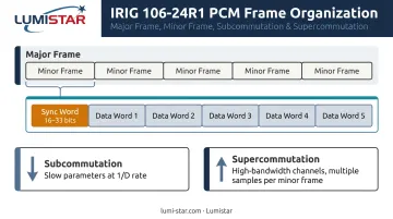
IRIG 106 also distinguishes Class I (basic PCM applications) from Class II (complex applications including bit rates exceeding 10 Mbps).
Bit Synchronization and Frame Sync
PCM telemetry streams arrive at the ground station as NRZ or bi-phase encoded serial data over an RF link. Before any data can be extracted, a bit synchronizer must lock onto the incoming stream, recover the bit clock, and present an aligned bit stream to the frame synchronizer. IRIG 106-24R1 permits NRZ codes (NRZ-L, NRZ-M, NRZ-S) and bi-phase codes (Bi-phi-L, Bi-phi-M, Bi-phi-S).
Clock jitter, signal fading, or a bit rate mismatch between transmitter and receiver are the primary causes of frame sync loss — and the result is corrupted measurement words, not just data gaps.
Decommutation and the PCM Map
Once frame sync is established, a PCM decommutator extracts individual measurement words from their assigned frame positions. The decommutator must be programmed with a PCM map specifying word positions, bit depths, and calibration parameters for every channel. A single-word offset in that map propagates silently — the engineering values look valid, just wrong.
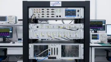
Getting the PCM map right demands hardware that can accommodate the full range of IRIG 106 format configurations. Lumistar's product line covers each stage of the decommutation chain:
- LS-50-E PCIe Decommutator: Supports minor frame lengths from 2 to 65,536 words, major frame lengths up to 1,024 minor frames, variable word length from 3 to 16 bits, and sync pattern configuration up to 64 bits.
- LS-45 Series Bit Synchronizers: Handle NRZ codes up to 45 Mbps and bi-phase codes up to 22.5 Mbps, with BER degradation below 1 dB from theoretical for NRZ signals under 20 Mbps.
- LS-68-M Integrated System: Combines bit synchronization, frame synchronization, decommutation, and real-time display in a single unit — IRIG 106 Class I and Class II compliant — for programs that need the full chain from RF reception through data archiving.
Common Misinterpretations of PCM in Practice
PCM Is Not Audio-Only
ITU-T G.701 defines PCM as a general digital transmission method. IRIG 106 applies the same mechanism to aeronautical telemetry. The underlying mathematics — sampling, quantization, binary encoding — is identical across telephony, audio, medical instrumentation, and flight test data.
What differs is the frame structure, synchronization patterns, and standards layered on top. Engineers crossing domain boundaries should expect the core terminology to carry over even when implementation details diverge significantly.
Sampling Rate and Bit Depth Are Not Interchangeable Quality Levers
This is the most common specification error. Sampling rate improves temporal resolution and frequency coverage. Bit depth improves amplitude precision and dynamic range. They control different things. An 8-bit system configured at 96 kHz will capture wideband frequency content and still quantize amplitude into only 256 discrete levels — that's measurable degradation in dynamic range regardless of how fast the sampling clock runs.
PCM and WAV Are Not the Same Thing
WAV is a container. PCM is an encoding method. Most WAV files contain LPCM data, which is why the terms get conflated — but a WAV file can legally contain compressed audio identified by a non-PCM format tag. Raw PCM has no header, no metadata, and no self-describing structure. Treating a raw PCM stream as a WAV file — or assuming a WAV file is always LPCM — will cause decoder errors in both cases.
These distinctions matter most when crossing domain boundaries or integrating systems built to different standards. Getting the terminology right is the first step to getting the configuration right.
Frequently Asked Questions
What does PCM data mean?
PCM (Pulse-Code Modulation) digitally represents an analog signal by sampling its amplitude at regular intervals, quantizing each sample to a binary value, and encoding the result as a bit stream. The method is used identically across audio systems, telephony, and telemetry data acquisition.
What is the sampling rate of PCM?
PCM has no single fixed sampling rate — it varies by application. Common rates include 8 kHz (telephony per ITU-T G.711), 44.1 kHz (CD audio), 48 kHz (professional audio), and 96 kHz (high-resolution archival). The governing rule is that the sampling rate must be at least twice the highest frequency present in the signal (Nyquist theorem).
Is PCM the same as WAV?
No. PCM is an encoding method; WAV is a container format. Most WAV files wrap LPCM-encoded audio with a metadata header, but the format can also carry compressed audio. Raw PCM has no header or file structure — it is a pure binary stream of sample values.
What is the PCM formula?
Data Rate = Sampling Rate × Bit Depth × Channels. Example: stereo CD audio = 44,100 samples/s × 16 bits × 2 channels = 1,411,200 bps (~1.41 Mbps). The same formula applies directly to telemetry PCM streams when sizing data links and storage.
What are PCM records in telemetry?
In telemetry, PCM records refer to the structured minor frames and major frames produced by a PCM decommutator — each record contains the extracted measurement values from individual sensor channels at their assigned frame positions. In audio contexts, the term may also refer to archival recordings stored in uncompressed PCM format.
Is PCM higher quality than MP3?
Uncompressed LPCM preserves the full sampled signal; MP3 uses lossy compression that permanently discards audio components judged perceptually less significant. For professional audio mastering, scientific measurement, and telemetry applications where signal integrity is non-negotiable, PCM is the correct choice.