Introduction
Engineers routinely write "C-band" into system specifications and procurement documents as if the label describes a single, uniform resource. It doesn't. C-band (4–8 GHz per IEEE definition) hosts satellite downlinks, 5G terrestrial services, radar altimeters, weather surveillance, Wi-Fi, and industrial ISM applications — each governed by a different regulatory framework with distinct guard bands and interference obligations.
Getting C-band characterization wrong has direct consequences. Free-space path loss calculations shift by over 7 dB between the band's lower and upper edges. Antenna aperture requirements change measurably when moving between C-band and adjacent Ku-band systems. And conflating the FCC's 3.7–4.2 GHz "C-band" with the full IEEE 4–8 GHz definition creates real procurement and interference analysis errors.
This guide covers what C-band frequency actually means across competing definitional frameworks, how its technical properties shape link budgets and antenna sizing, where the genuine operational pitfalls are, and what engineers need to verify before writing "C-band" into a system specification.
Key Takeaways
- IEEE definition: C-band spans 4.0–8.0 GHz, wavelength 3.75–7.5 cm, within ITU's Super High Frequency (SHF) range
- FCC "C-band" ≠ IEEE C-band: The FCC's 5G proceeding defined it as 3.7–4.2 GHz (not 4.0–8.0 GHz) — don't conflate the two
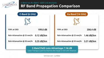
- Rain fade advantage: C-band (6 GHz) attenuates ~0.12 dB/km at 25 mm/hr rain versus ~1.46 dB/km at Ku-band (14 GHz)
- Path loss trade-off: C-band (6 GHz) incurs ~199 dB FSPL at GEO versus ~206 dB at 14 GHz, a 7.36 dB advantage
- Antenna size is real: Achieving equivalent gain at C-band requires larger physical apertures than Ku-band — a direct consequence of longer wavelengths
What C-Band Frequency Represents in Microwave RF Systems
IEEE defines C-band as 4.0 to 8.0 GHz, corresponding to wavelengths of 3.75 to 7.5 centimeters. This places it entirely within the ITU's Super High Frequency (SHF) classification, which spans 3–30 GHz. The "C" designation is a standardized historical radar letter — not an acronym — originating from WWII U.S. military secrecy conventions and later formalized by IEEE in its 1976 radar band standard.
Frequency isn't just a label — it governs every aspect of how a link performs in the field:
- Free-space path loss magnitude
- Antenna aperture required for a given gain
- Atmospheric interaction (rain, oxygen absorption)
- Available bandwidth and spectral efficiency
- Regulatory permissibility for a given geographic region and application
Engineers select C-band deliberately, weighing link range, propagation requirements, power constraints, and applicable regulatory allocations. Those propagation characteristics are where C-band earns its place.
Why C-Band Occupies a Propagation Sweet Spot
C-band sits above the frequencies where atmospheric oxygen and water vapor absorption meaningfully affect link performance, but well below the threshold where rain attenuation becomes a dominant concern. Millimeter-wave bands (Ka at 26–40 GHz, V at 40–75 GHz) suffer serious rain fade that requires active uplink power control to maintain availability. L-band and S-band avoid rain fade but offer narrower absolute bandwidths and require even larger antennas for equivalent gain.
This makes C-band practical for long-distance links that need to survive adverse weather without the infrastructure overhead of aggressive fade mitigation.
The C-Band Frequency Range: Boundaries, Sub-Bands, and Variants
The full 4–8 GHz range is not a single allocation. It is partitioned into distinct operational sub-bands, each with its own regulatory framework — and engineers must specify which sub-band applies to their system, not just invoke the IEEE label.
Standard C-Band (Satellite Communications)
Per 47 CFR 25.202, Standard C-band satellite use is defined as:
- Downlink (space-to-Earth): 3,700–4,200 MHz
- Uplink (Earth-to-space): 5,925–6,425 MHz
Note that the satellite downlink extends below the IEEE C-band lower boundary of 4.0 GHz, reaching into what IEEE classifies as S-band territory. This mismatch is a known specification trap — "C-band satellite downlink" and "IEEE C-band" do not share identical lower boundaries.
Extended C-band adds further capacity: downlink at 3,400–3,700 MHz, uplink at 6,425–6,725 MHz. Availability is region-specific and governed by ITU regional coordination agreements across Regions 1, 2, and 3.
According to ITU News, C-band satellite capacity is equivalent to more than 3,000 transponders of 36 MHz bandwidth globally — a figure that illustrates the band's continued importance despite pressure from 5G terrestrial reallocation.
5G and FCC C-Band Allocation
The FCC's definition of "C-band" diverges significantly from IEEE. FCC Order 20-22 designated 3.7–4.2 GHz for flexible/5G terrestrial use, structured as:
| Segment | Frequency | Use |
|---|---|---|
| Flexible use (5G) | 3.70–3.98 GHz | Auctioned in FCC Auction 107 (December 2020) |
| Guard band | 3.98–4.00 GHz | 20 MHz protection zone |
| Repacked FSS | 4.00–4.20 GHz | Satellite operators relocated here |
A specification that references "C-band" without distinguishing IEEE 4–8 GHz from FCC 3.7–4.2 GHz creates a 300 MHz boundary discrepancy — enough to drive receiver selection errors and link budget miscalculations in flight test systems.
Additional Sub-Band Allocations
The FCC/IEEE divergence is only part of the picture. Within the same 4–8 GHz span, multiple incumbent services hold protected allocations that any new system must account for:
- 4.2–4.4 GHz: Aeronautical Radionavigation Service (ARNS), reserved exclusively for radar altimeters under ITU RR No. 5.438
- 5.725–5.875 GHz: ISM band (47 CFR 18.301), used for industrial, scientific, and medical devices
- 5.15–5.895 GHz: U-NII/Wi-Fi allocations under 47 CFR 15.407
- 5.650–5.925 GHz: Amateur radio (47 CFR 97.301)
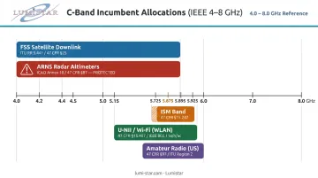
Any system operating within IEEE C-band faces co-channel interference risk from several of these incumbents at once. Overlapping allocations are the rule here, not the exception.
Key Technical Properties of C-Band Frequencies
C-band's engineering value comes from four interrelated physical properties. They cannot be optimized independently — improving one typically trades off another.
Atmospheric Propagation and Rain Fade Resistance
ITU-R P.838-3 provides the specific rain attenuation model: γ_R = k R^α, where R is rain rate in mm/h and γ_R is attenuation in dB/km.
At a rain rate of 25 mm/hr, the attenuation difference is significant:
| Frequency | Specific Attenuation |
|---|---|
| 6 GHz (C-band) | ~0.12 dB/km |
| 14 GHz (Ku-band) | ~1.46 dB/km |
At 50 mm/hr, C-band attenuation reaches approximately 0.35 dB/km while Ku-band climbs to roughly 3.21 dB/km. The physical explanation: C-band wavelengths (3.75–7.5 cm) are substantially larger than most raindrop diameters, limiting both absorption and scattering. Ku-band wavelengths fall closer to raindrop size, making the interaction far more pronounced.
Satellite broadcasters, enterprise VSAT networks, and disaster recovery links have historically relied on C-band for exactly this reason — link availability cannot be compromised on mission-critical paths.
Free-Space Path Loss and Link Budget Implications
Free-space path loss follows the ITU-R P.525-3 formula:
L_bf (dB) = 32.4 + 20log₁₀(f_MHz) + 20log₁₀(d_km)
At GEO satellite distance (35,786 km), this produces:
| Frequency | FSPL |
|---|---|
| 6,000 MHz (C-band) | 199.0 dB |
| 14,000 MHz (Ku-band) | 206.4 dB |
C-band carries a 7.36 dB path loss advantage over Ku-band on the same link. Within C-band itself, moving from the lower edge (4 GHz) to the upper edge (8 GHz) adds approximately 6 dB of path loss — a link budget impact that must be accounted for when specifying equipment across the full IEEE band range.
Antenna Aperture Requirements
Antenna gain scales with aperture area relative to wavelength squared. At lower C-band frequencies, achieving a target gain level requires a physically larger dish than at Ku or Ka-band. The ground infrastructure is heavier and more expensive — the direct trade-off against C-band's lower path loss.
For satellite reception, typical dish sizes by band:
- C-band: 1.8–3.5 meters diameter
- Ku-band: 0.6–0.9 meters for equivalent installations
Larger apertures provide one compensating benefit: narrower beamwidth, which improves interference rejection from adjacent satellites on the geostationary arc. In congested orbital slot environments, that selectivity matters.
Available Bandwidth and Spectral Efficiency
The IEEE C-band definition spans 4 GHz of total spectrum, but usable allocations are heavily fragmented. After the FCC repack, U.S. satellite operators retain only 200 MHz of downlink spectrum (4.0–4.2 GHz). Transponder bandwidth runs approximately 36 MHz per transponder, limiting throughput capacity per carrier.
Higher-order modulations (64-QAM and above) place tighter demands on phase noise and frequency accuracy from C-band RF hardware. DVB-S2 and DVB-S2X implementations address this through phase noise masks and C/N degradation tables defined in ETSI EN 302 307. Hardware selection must match the modulation scheme's stability requirements.
C-Band Applications Across Aerospace, Satellite, and Wireless Systems
C-band's practical footprint spans several distinct engineering domains:
Satellite communications: Full-time TV network distribution, enterprise VSAT networks, and disaster recovery links rely on C-band's rain fade resilience and established infrastructure. Standard C-band remains the backbone of international broadcast distribution despite ongoing spectrum pressure from 5G.
Weather radar: Meteorological C-band radar operates around 5,250–5,850 MHz, balancing rain sensitivity (sufficient to detect precipitation at meaningful ranges) against spatial resolution. C-band weather systems offer better range performance than X-band alternatives and better sensitivity than S-band at moderate distances.
5G mid-band terrestrial wireless: The FCC's 3.7–3.98 GHz allocation (3GPP bands n77/n78) provides the coverage-throughput balance between low-band and millimeter-wave 5G — wide-area coverage with substantially higher throughput than 700 MHz or 850 MHz deployments.
Aeronautical radionavigation: Radar altimeters operate exclusively in the 4.2–4.4 GHz ARNS allocation. These systems are safety-critical — altitude measurement from ground return is a flight-critical parameter, which is why the proximity of 5G deployments to the 4.0–4.2 GHz FSS downlink became a significant regulatory issue.
Particle accelerators: SLAC and other U.S. facilities operate C-band linear accelerator RF power sources at 5.712 GHz, extending C-band RF engineering into high-energy physics research.
C-Band Considerations in Flight Test and Aeronautical Telemetry
For the flight test community specifically, IRIG 106-governed telemetry frequency bands are primarily in L-band and S-band, but C-band adjacency creates real engineering obligations at test ranges. The aeronautical ARNS allocation at 4.2–4.4 GHz sits immediately above the FCC-repacked satellite downlink at 4.0–4.2 GHz — a boundary with known interference sensitivity.
Lumistar's telemetry receivers and ground station systems — including the LS-28-DRSM series and LS-27-M tracking receivers — support C-band operation across C1 (4,400–4,940 MHz) and C2/C2e (5,091–5,250 MHz) bands, in addition to L-band and S-band IRIG 106 allocations.
The LS-28-DRSM's dual SAW and DSP FIR filtering architecture delivers over 40,000 automatically optimized IF bandwidth selections, providing adjacent channel interference rejection that exceeds IRIG requirements — directly relevant when C-band incumbents operate near telemetry reception frequencies.
Frequency coordination at test ranges requires accounting for all active C-band allocations in the geographic area. Interference candidates that affect antenna placement and LNA front-end filter selection include:
- Satellite earth station downlinks (4.0–4.2 GHz)
- ISM-band emitters
- 5G mid-band infrastructure (3.7–3.98 GHz)
- Aeronautical ARNS-protected operations (4.2–4.4 GHz)
Regulatory Definitions, Documentation Standards, and Measurement Practice
The Definitional Divergence Problem
Four separate frameworks define "C-band" differently:
| Framework | C-Band Definition |
|---|---|
| IEEE (radar bands) | 4.0–8.0 GHz |
| ITU (SHF) | 3.0–30 GHz (C-band is a subset) |
| FCC (5G proceeding) | 3.7–4.2 GHz |
| NATO ECM (legacy) | 0.5–1.0 GHz (obsolete) |
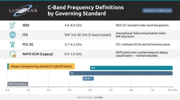
Every system specification document must explicitly identify which standard governs the frequency definition. A procurement document that lists "C-band receiver" without a regulatory reference is inherently ambiguous.
Allocation references span several authoritative sources:
- ITU Radio Regulations Volume 1
- FCC Part 25 (satellite earth stations)
- NTIA frequency allocation charts
- IRIG 106 for aeronautical telemetry
Any component labeled "C-band" in a datasheet must be verified against the applicable allocation table for the specific geographic region and application type before entering a system design.
Measurement and Verification
Field verification at C-band requires careful setup. Key equipment requirements include:
- Spectrum analyzers covering the relevant sub-band with adequate resolution bandwidth for guard band compliance and spurious emission measurement
- Signal generators calibrated for carrier offset testing to verify transponder spacing
Field measurement accuracy is degraded by ambient thermal noise, multipath, and adjacent satellite interference — conditions that do not replicate lab calibration environments. Link budget models validated in the lab require additional margin when applied to field deployments, particularly for low-elevation angle paths where ground radiation significantly increases effective system noise temperature.
Boundary Conditions and Operational Pitfalls
The 5G/Altimeter Boundary Problem
The most consequential C-band boundary condition involves three adjacent allocations stacked within roughly 400 MHz:
- 3.98–4.00 GHz: FCC guard band
- 4.00–4.20 GHz: Repacked FSS satellite downlink
- 4.20–4.40 GHz: ARNS radar altimeter (flight safety critical)
Operating 5G base stations in the 3.7–3.98 GHz band near airports creates potential out-of-band interference into the 4.2–4.4 GHz altimeter allocation through receiver desensitization and intermodulation. The FAA issued safety guidance on this concern in 2021–2022, leading to temporary restrictions near major U.S. airports pending altimeter equipment upgrades and coordination — an outcome driven entirely by the gap between adjacent frequency assignments and mismatched safety criticality levels.
The Full-Band Availability Misinterpretation
The most common specification error at C-band is treating the full IEEE 4–8 GHz range as uniformly available. Actual usable spectrum is far narrower:
- Most operational systems use narrow segments of the 4 GHz total span
- The FCC's satellite repack compressed FSS into just 200 MHz of the original 500 MHz downlink allocation
- ISM, Wi-Fi, amateur, and ARNS allocations consume significant portions of upper C-band
- Frequency coordinators must work from the applicable sub-band table, not the IEEE band label
Conflating the FCC's "C-band" (3.7–4.2 GHz) with IEEE C-band (4–8 GHz) produces errors in interference analysis, equipment procurement specifications, and regulatory filings.
Link Budget Margins in Real-World Deployments
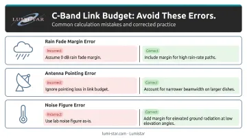
Spectrum planning errors aren't the only pitfall. Three calculation errors appear repeatedly in C-band link budget design:
Assuming C-band is immune to rain fade. It isn't — it's more resilient than Ku-band, but margin must still be included. Engineers who over-correct sometimes set rain fade margin to zero for C-band links, which fails on high-rain-rate paths.
Ignoring antenna pointing error. Gain loss from pointing error at C-band is measurable and worsens with dish size. A 3-meter dish has a narrower beamwidth than a 1.8-meter dish — precise tracking matters more, not less.
Using laboratory noise figures in field conditions. Low-elevation C-band paths see increased thermal noise from ground radiation, raising effective system noise temperature and reducing actual SNR below the predicted value.
Frequently Asked Questions
What is C-band RF?
C-band RF refers to the IEEE-designated microwave frequency band spanning 4.0 to 8.0 GHz, with wavelengths of 3.75 to 7.5 centimeters. It falls within ITU's Super High Frequency (SHF) classification and is used for satellite communications, weather radar, Wi-Fi, and aeronautical radionavigation.
What frequency is the C-band?
The IEEE definition is 4–8 GHz, but the applicable frequency depends on the regulatory framework. The FCC designated 3.7–4.2 GHz as "C-band" for 5G; standard satellite downlink runs 3.7–4.2 GHz and uplink runs 5.925–6.425 GHz. Any specification should identify which framework governs.
What is C-band frequency used for?
Primary applications include satellite TV broadcasting and enterprise VSAT networks, weather radar (5.25–5.85 GHz), 5G mid-band wireless at 3.7–3.98 GHz, aeronautical radar altimeters at 4.2–4.4 GHz, Wi-Fi at 5 GHz, and ISM-band devices at 5.8 GHz.
Does C-band require a large antenna?
C-band's longer wavelength requires a larger aperture to achieve equivalent gain compared to Ku-band. Satellite receive dishes typically measure 1.8–3.5 meters for C-band reception versus 0.6–0.9 meters for Ku-band, a direct consequence of the gain-aperture-wavelength relationship.
How does C-band compare to Ku-band for satellite communications?
C-band offers significantly lower rain fade susceptibility (approximately 0.12 dB/km versus 1.46 dB/km at 25 mm/hr rain rate) and a ~7.4 dB path loss advantage at GEO distance. Ku-band supports higher throughput with smaller antennas but requires active fade mitigation. Choose based on link availability requirements, antenna budget, and deployment geography.
What is the difference between Standard and Extended C-band?
Standard C-band uses 5.925–6.425 GHz uplink / 3.7–4.2 GHz downlink. Extended C-band adds 6.425–6.725 GHz uplink / 3.4–3.7 GHz downlink for additional capacity. Geographic availability for the extended allocation depends on ITU regional coordination agreements and national regulatory decisions.