The design challenge is real: combining RF signals introduces insertion loss, potential impedance mismatches, and inter-port crosstalk. Choose the wrong topology or overlook a key parameter, and system-level performance degrades in ways that are difficult to diagnose after integration.
This article covers the foundational concepts engineers need: what combiners do, the performance parameters that matter, the three primary topologies (resistive, reactive, Wilkinson), even/odd mode analysis, and how these principles apply in aerospace telemetry and flight test systems.
Key Takeaways
- RF combiners and splitters are the same reciprocal device — direction of signal flow determines function
- Two 50-ohm lines joined in parallel present 25 ohms, causing reflections without a combiner
- Resistive combiners offer wideband flatness but carry 6 dB total insertion loss
- Wilkinson combiners achieve 20+ dB isolation with near-lossless in-band combining (typically <0.5 dB insertion loss) at a target frequency
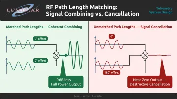
- In aerospace telemetry combining, path length imbalance between input signals causes phase mismatch and signal cancellation
What Is an RF Combiner and How Does It Work?
An RF combiner is a passive, typically three-port device that merges two or more input signals into a single output. Most combiners and splitters are reciprocal — the same physical component performs both functions depending on which ports carry the input signal. Mini-Circuits documents this directly: apply signals to the output ports and the vector sum appears at the common port.
The Impedance Problem a Combiner Must Solve
Simply joining two transmission lines at a node creates an immediate problem. Two 50-ohm lines connected in parallel present 25 ohms to a 50-ohm source. That mismatch causes reflected power, poor return loss, and standing waves throughout the system.
A combiner's job is to resolve this while preserving signal integrity. Using Keysight's return loss definition — RL = -20 log₁₀|Γ| — even a modest impedance mismatch generates measurable reflected power. VSWR, expressed as (1 + |Γ|)/(1 - |Γ|), conveys the same mismatch data in ratio form — the format most RF datasheets use for quick spec comparisons.
Combining vs. Splitting — and Why Isolation Matters
Combining and splitting are directional functions — the same hardware serves both roles depending on signal flow. Once that's understood, the real design challenge shifts to isolation: how effectively the combiner prevents energy from one input port reaching another.
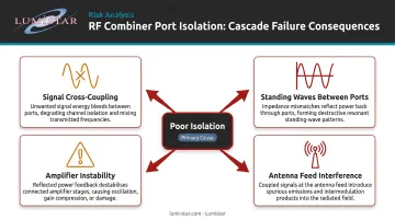
Poor isolation creates problems that compound quickly:
- Signals from independent sources corrupt each other through cross-coupling
- Standing waves develop between input ports, degrading match
- Separate amplifiers interact, risking instability or output distortion
- Independent antenna feeds produce interference rather than a clean combined signal
Key Performance Parameters of RF Combiners
Understanding these five parameters lets you evaluate any combiner topology against your system requirements.
Insertion Loss
Insertion loss is the signal attenuation from any input port to the output. Two types exist:
- Inherent split loss — a 2-way split carries an unavoidable 3 dB reduction (half the power to each port); N-way splitting follows 10·log(N) dB
- Excess loss — additional attenuation from resistive dissipation or imperfect matching
The Marki PD-0030 resistive divider, covering DC to 30 GHz, shows 6 dB nominal power splitting with 0.5 dB typical excess insertion loss. A Wilkinson design like the Knowles/DLI PDW06407 (2–18 GHz) shows 3.0 dB nominal split loss with 2.5 dB typical excess — better than resistive at frequency, but only within its operating band.
Port Isolation
Isolation is the attenuation between two input ports. Microwaves101 states that an ideal resistive 3-port splitter has isolation equal to its insertion loss — roughly 6 dB. The Knowles/DLI PDW06407 Wilkinson specifies 20 dB minimum isolation, making topology selection a direct function of how much inter-port crosstalk your system can tolerate.
Return Loss and VSWR
Return loss measures impedance match quality at each port. The PDW06407 specifies 14 dB minimum / 18 dB typical return loss. The Marki PD-0030 specifies 1.2 typical VSWR. Higher return loss means less reflected power reaching upstream components — critical for protecting low-noise amplifiers and receivers.
Amplitude and Phase Balance
Ideal combiners produce equal amplitude and phase at all ports. In practice:
- Marki PD-0030: 0.25 dB typical amplitude balance, 2° typical phase balance
- Knowles/DLI PDW06407: ±0.25 dB amplitude balance, ±5° phase balance
Imbalance in phased array or antenna diversity systems causes signal cancellation — a combiner with 10° phase imbalance can measurably degrade combining gain.
Bandwidth
- Resistive combiners: essentially flat from DC to tens of GHz (limited by component parasitics)
- Quarter-wave reactive/Wilkinson: inherently narrowband around the design frequency
- Multi-section Wilkinson: Mini-Circuits AN10-003 documents a design covering 500–5000 MHz — a 10:1 bandwidth — with 0.8 dB typical 2-way insertion loss
RF Combiner Topologies: From Simple to High-Performance
Resistive (R-Network) Combiners
Resistive combiners use only resistors (in star/wye or delta configurations) to achieve impedance matching at all frequencies simultaneously.
For a 50-ohm 3-port wye network, the matched star arm value is Z₀/3 = 16.7 ohms. The delta equivalent uses resistors equal to Z₀ = 50 ohms. No frequency-dependent elements means the response is flat from DC to the component's parasitic limit.
The tradeoff is significant: 6 dB total insertion loss per port (3 dB from splitting, 3 dB dissipated in resistors). Isolation also equals insertion loss — a modest ~6 dB between input ports.
Best applications:
- Broadband signal monitoring
- Laboratory test setups
- Low-power signal distribution where wideband flatness outweighs efficiency
Reactive (T-Junction and Quarter-Wave) Combiners
Where resistive combiners sacrifice efficiency for flatness, reactive combiners recover that loss — at the cost of bandwidth. A T-junction combiner joins transmission lines directly. Two 50-ohm branches in parallel present 25 ohms at the junction, a mismatch that requires a quarter-wave transformer to correct.
The transformer characteristic impedance is the geometric mean of source and load: Z_T = √(Z_S × Z_L). For converting 25 ohms back to 50 ohms, Z_T = √(25 × 50) ≈ 35.4 ohms. This works at the design frequency but degrades rapidly away from it.
The T-junction provides no port-to-port isolation. Any reflection from one arm propagates directly into the other, making it sensitive to load variations. It works in tightly matched systems but fails when independent signal sources need protection from each other.
T-junction limitations at a glance:
- No isolation between input ports
- Bandwidth limited to a narrow window around the design frequency
- Susceptible to load mismatch from either branch
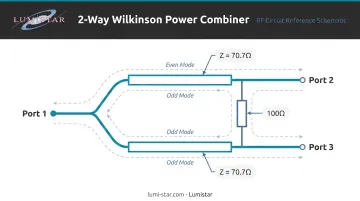
Wilkinson Power Combiner
The T-junction's isolation problem was solved in 1960, when Ernest J. Wilkinson published his combiner design in IRE Transactions on Microwave Theory and Techniques. It achieves low insertion loss and high port-to-port isolation simultaneously.
Design rules for a 50-ohm system:
- Two quarter-wave transmission line arms with Z = Z₀√2 ≈ 70.7 ohms
- Each arm transforms to 100 ohms; two in parallel give 50 ohms at the input
- Isolation resistor between output ports: 2Z₀ = 100 ohms
The isolation resistor absorbs odd-mode energy (signals that would otherwise couple from one input port to the other) without affecting in-phase signals at all.
Wilkinson Combiner Design: Even and Odd Mode Analysis
Even/odd mode analysis is the standard mathematical technique for solving symmetric two-port networks like the Wilkinson. Any arbitrary input decomposes into an in-phase (even mode) component and an out-of-phase (odd mode) component, analyzed independently.
Even Mode Analysis
When both input ports receive identical in-phase signals, no voltage difference exists across the isolation resistor — so no current flows through it. Each arm acts as an independent quarter-wave transformer, and signals combine coherently at the output with minimal loss. The resistor is electrically invisible during even-mode excitation.
Odd Mode Analysis
When input ports receive equal but opposite-phase signals, a virtual ground appears at the symmetry plane. The isolation resistor now connects each arm to virtual ground. With the resistor set to 2Z₀ = 100 ohms, it perfectly absorbs the odd-mode energy — preventing it from reaching the opposite port or reflecting back toward the source.
S-Parameter Results
Ansys documents the ideal Wilkinson S-parameters as:
| Parameter | Ideal Value | Meaning |
|---|---|---|
| S₁₁ = S₂₂ = S₃₃ | 0 | Perfect match at all ports |
| S₂₁ = S₃₁ | -j/√2 | Equal 3 dB power split |
| S₂₃ | 0 | Perfect inter-port isolation |
Real implementations deviate from these ideals across bandwidth. The isolation resistor is what simultaneously maintains port match and isolation; without it, the network reverts to a simple T-junction with no isolation between output ports.
Bandwidth Extension
The quarter-wave sections are inherently frequency-specific. For wider bandwidth:
- Multi-section (cascaded) stages stack multiple Wilkinson dividers to extend bandwidth, trading physical size for frequency range
- Coupled-line designs can achieve wide fractional bandwidths — a 2023 IEEE design achieved 23+ dB output isolation across 53.3% fractional bandwidth
Both approaches increase complexity but are often necessary for systems spanning multiple telemetry bands.
Practical RF Combiner Design Considerations
Substrate and Impedance Selection
Substrate dielectric constant (Dk) determines the physical length of quarter-wave sections. Rogers RO4003C laminate, commonly used in microwave combiner designs, has a design Dk of 3.55 and dissipation factor of 0.0027 at 10 GHz — properties that define both line length and achievable insertion loss at frequency.
At frequencies above a few GHz, substrate selection is not a secondary concern. A higher-loss substrate directly adds to excess insertion loss, eroding the efficiency advantage that justified choosing a Wilkinson over a resistive design.
Power Handling and the Isolation Resistor
The isolation resistor must handle worst-case odd-mode power dissipation. For reference:
- Vishay FC series thin-film chip resistors for high-frequency use specify 50 mW for a 0402 package
- The Knowles/DLI PDW06407 complete 2–18 GHz Wilkinson specifies 5 W typical input power
In multi-port or high-power combining applications — such as power amplifier output combining — resistor power rating and thermal management become critical constraints. Size the resistor for the maximum imbalance case, not nominal operation.
Phase and Path Length in Multi-Way Designs
In N-way combiners beyond 2-way, equal electrical path lengths to all input ports are non-negotiable for coherent combining. Unequal paths introduce phase-dependent signal cancellation. Mini-Circuits notes that a 2-way combiner with equal-amplitude, in-phase inputs produces zero insertion loss; with 180° out-of-phase inputs, loss becomes theoretically infinite. That full range of outcomes — from perfect combining to complete cancellation — hinges entirely on path length control.
RF Combiners in Aerospace Telemetry and Flight Test Systems
RF combining is embedded in the architecture of every serious telemetry ground station. Antenna systems using multiple elements or dual-polarization feeds must combine signals before they reach the receiver, and the combiner's performance directly determines how much link margin the ground station preserves during high-dynamic flight profiles.
Telemetry Frequency Band Requirements
Per IRIG 106-20, aeronautical telemetry operates across defined bands:
| Band | Frequency Range |
|---|---|
| Lower L-band | 1435–1525 MHz |
| Lower S-band | 2200–2290 MHz |
| Upper S-band | 2310–2395 MHz |
| Lower C-band | 4400–4940 MHz |
| Middle C-band | 5091–5150 MHz |
A combiner serving a multi-band ground station must maintain insertion loss, isolation, and return loss specifications across this range — a nearly 4:1 ratio from L-band to C-band. Single-section Wilkinson designs cannot cover this span; wideband or switchable architectures are required.
Phase Sensitivity in Ground Station Combining
RCC 120-21 warns explicitly that engineers avoid 50/50 splits when multiple antennas may simultaneously receive the same aircraft. Signals arriving at two antenna elements with a relative phase difference approaching 180° will cancel in a simple power combiner. This is the same failure mode the Wilkinson isolation resistor prevents between independent sources, but in coherent antenna combining, phase-path management must address it directly.
That phase cancellation risk is precisely why diversity combining matters. The same document reports that optimal-ratio combining improves data quality by approximately 2.5 dB in practice when input signals are equal in amplitude and phase, confirming that the theoretical advantage translates to measurable link margin improvement.
Lumistar's Approach to Telemetry Diversity Combining
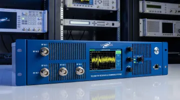
Lumistar's LS-28-DRSM Series integrates diversity combining directly into the receiver architecture, supporting dual-channel reception across up to six RF bands from 200 MHz to 6 GHz. The system implements digital Pre-D combining with a break frequency exceeding 50 kHz (critical for rapid multipath fading in high-dynamic profiles) and achieves greater than 2.6 dB typical S/N improvement in Optimal Ratio mode.
Three product lines address different points in the ground station RF chain:
- LS-28-DRSM Series: Dual-channel Pre-D combining across up to six bands (200 MHz–6 GHz), with >2.6 dB S/N improvement in Optimal Ratio mode
- LS-35-R IF Receiver/Combiner: Real-time Eb/N₀ algorithm supporting polarization, frequency, and spatial diversity combining; Post-D combining available
- LS-16 Series Multicouplers: RF signal distribution with 50 dB minimum output-to-output isolation from 300 MHz to 6 GHz, well beyond what passive resistive combiners provide
All three systems interface at 50-ohm SMA inputs, compatible with standard RF distribution hardware. Lumistar's engineering team brings over 100 years of combined experience focused specifically on aeronautical flight test, and every product is designed and manufactured in the USA.
Frequently Asked Questions
What is the difference between an RF combiner and an RF splitter?
They are the same physical device used in reverse. A splitter takes one input and delivers copies to multiple output ports; a combiner takes multiple inputs and merges them at one output port. The component is reciprocal: signal direction determines the function.
Why does a resistive combiner have 6 dB of insertion loss instead of 3 dB?
A 2-way split inherently reduces power by 3 dB, since half goes to each port. The resistors in a resistive combiner dissipate an additional 3 dB to maintain impedance matching at all ports simultaneously, totaling 6 dB loss per output.
What makes the Wilkinson combiner better than a simple T-junction combiner?
The Wilkinson adds an isolation resistor between the output arms that absorbs odd-mode (out-of-phase) energy. This achieves 20+ dB inter-port isolation and matched impedance at all ports, two characteristics a bare T-junction cannot provide.
How does isolation work in an RF combiner?
Isolation is the attenuation between two input ports. The isolation resistor in a Wilkinson combiner dissipates any out-of-phase signal component that would otherwise couple from one input to the other, protecting each signal source from the other.
How do I choose the right RF combiner topology?
Use a resistive combiner when you need broadband operation and can tolerate 6 dB insertion loss. Use a Wilkinson when low loss and high isolation matter over a defined frequency band. Use multi-section Wilkinson or coupled-line designs when you need wide bandwidth with low loss.
Can a Wilkinson combiner handle unequal power inputs?
When inputs have unequal amplitude or phase, the odd-mode component is partially absorbed by the isolation resistor, generating heat and reducing combining efficiency. Equal-amplitude, in-phase inputs are required for optimal coherent combining performance.