Introduction
FEC decoding is the receiver-side process where a decoder uses redundant parity data — added during transmission — to detect and correct bit errors without retransmission. For engineers working in aeronautical flight test, aerospace, and defense, this distinction matters enormously: when the data stream goes silent or corrupts, you cannot ask for it again.
Many technical teams treat the decoder as a black box. The demodulator feeds it bits, and corrected data comes out the other side. That assumption holds right up until a critical maneuver, when a misconfigured or overloaded decoder means irreplaceable test data is gone for good.
This guide covers how FEC decoding works from encoder handoff through data reconstruction, the major decoder types and their trade-offs, and the operational factors that determine whether a decoder performs or fails in challenging RF environments.
Key Takeaways
- FEC embeds redundancy at the transmitter so the receiver can correct errors without retransmission
- Decoding is code-specific: Reed-Solomon, LDPC, and convolutional codes each use distinct algorithms
- Hard-decision decoders make binary bit calls before correction; soft-decision decoders use channel probability data, typically adding 2–3 dB of coding gain
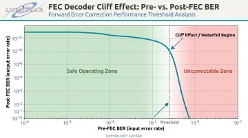
- Every FEC decoder has a pre-FEC BER threshold — cross it, and post-FEC output collapses rapidly (the "cliff effect")
- In aeronautical telemetry, FEC decoding is the only error recovery mechanism on a one-way downlink
What Is FEC Decoding?
As defined by ITU-T Recommendation X.141, forward error correction is a coding method used to detect and correct errors in received data instead of requesting retransmission. FEC decoding is the receiver-side implementation of that principle: the decoder takes an incoming encoded bitstream — composed of original data bits and appended parity/redundancy bits — and applies a decoding algorithm to identify where transmission errors occurred and restore the original data.
Decoding vs. Encoding
Encoding adds structure and redundancy at the transmitter. Decoding reverses that process at the receiver. IRIG 106-15 Appendix R is explicit on this point: the telemetry link requires an encoder on the transmission side and a decoder on the receiving side — two distinct operations, two distinct hardware implementations.
Both ends must follow identical rules. Same code type, same code rate, same generator or parity-check matrix. A parameter mismatch produces complete data loss — not degraded data. In multi-vendor flight test systems, this is one of the most common integration failure points and should be validated explicitly during system design.
FEC Decoding vs. ARQ
Automatic Repeat reQuest (ARQ) detects errors and requests retransmission from the sender. FEC decoding corrects errors using redundancy already embedded in the signal — no retransmission required. The practical difference comes down to link architecture:
- ARQ requires a bidirectional link between transmitter and receiver
- FEC operates on a one-way signal, making it the standard for aeronautical telemetry downlinks
- Latency impact: ARQ adds round-trip delay; FEC correction happens in real time at the decoder
Why FEC Decoding Is Critical in Aeronautical Telemetry
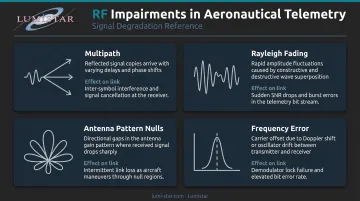
Flight test RF environments are unforgiving. IRIG 106-20 and related RCC documentation describe the specific impairments telemetry signals face from moving platforms:
- Multipath — a three-ray model with line-of-sight, specular reflection, and diffuse reflection terms creates destructive interference
- Rayleigh fading — signal amplitude fluctuates as the aircraft maneuvers, with fade-depth probability that can briefly drop the link below usable thresholds
- Antenna pattern nulls — the two-antenna problem creates large variance in test-article antenna gain, producing bursty link degradation
- Frequency error — single-carrier waveforms like SOQPSK-TG face frequency-error bounds that the receiver must accommodate
Without FEC, raw bit error rates in these conditions can easily render telemetry data unusable.
Why Retransmission Isn't Available
Each of these impairments compounds the others, and there is no fallback path at the link layer. Packet telemetry in aeronautical flight test operates as a downlink. IRIG 106-15 Chapter 7 addresses this directly: there is no uplink path for the ground station to request retransmission of corrupted data during a typical flight test event. FEC decoding is the sole mechanism for error recovery.
IRIG 106 Standards Coverage
IRIG 106 specifies FEC coding requirements across multiple sections:
| IRIG 106 Reference | FEC Coverage |
|---|---|
| Chapter 2, Section 2.5 | Codes for telemetry systems |
| Chapter 7, Section 7.2.1 | Reed-Solomon error correction for packet telemetry |
| Chapter 7, Section 7.5 | LDPC and Reed-Solomon error correction techniques |
| Appendix 2-D | LDPC codes |
| Appendix R | LDPC codes for aeronautical mobile telemetry (AMT) |
Modern ground station receivers, including Lumistar's LS-28-DRSM and LS-18 series, integrate FEC decoding as a core processing stage between demodulation and data output, consistent with these IRIG 106 requirements.
How FEC Decoding Works
The received signal contains the original data plus redundant bits, but some bits may have been flipped by channel noise. The decoder uses knowledge of the encoding rules — expressed as a parity-check matrix, a trellis, or a factor graph — to determine the most likely original data sequence and output corrected bits.
Before decoding begins, many FEC systems require a deinterleaving step. Interleavers spread burst errors across multiple codewords during transmission, making them easier to correct. At the receiver, the deinterleaver reverses this permutation before the decoder is applied. This adds latency, which must be managed in real-time telemetry systems where downstream processing has strict timing constraints.
Step 1: Syndrome Computation or Likelihood Estimation
The decoder's first task depends on whether it uses hard or soft decisions:
- Hard-decision decoding: The decoder computes a syndrome — a check value derived from the received codeword that reveals whether errors are present and provides location information
- Soft-decision decoding: Instead of immediate binary decisions, the decoder computes log-likelihood ratios (LLRs) for each received bit, capturing the probability that each bit is 0 or 1 based on the analog channel output
LLR-based processing preserves channel reliability information that hard-decision decoding discards, which is where the additional coding gain comes from.
Step 2: Error Location and Correction
Each decoder type uses a different algorithm to identify and correct error positions:
- Reed-Solomon: The Berlekamp-Massey algorithm solves for error locations and magnitudes algebraically within the symbol space
- Viterbi (convolutional): Traces the maximum-likelihood path through a code trellis
- LDPC: Runs iterative message-passing (belief propagation) on a bipartite graph, passing probability estimates between variable nodes and check nodes across multiple iterations
- Turbo: Two parallel soft-in/soft-out (SISO) constituent decoders exchange extrinsic information iteratively
Step 3: Output, BER Monitoring, and the Cliff Effect
Corrected data passes to the output. Simultaneously, pre-FEC BER (entering the decoder) and post-FEC BER (leaving the decoder) must be monitored.
The cliff effect is critical for link margin planning. FEC decoders exhibit sharp threshold behavior: above a critical pre-FEC BER, post-FEC performance collapses rapidly rather than degrading gracefully. JPL IPN Progress Report 42-142 describes this as the "waterfall" region where BER versus Eb/N0 changes most abruptly. Designers who skip worst-case channel verification are assuming FEC will always recover data. That assumption can result in undetected total data loss during critical test events.
For operators managing this in the field, Lumistar's LS-28-DRSM-R1 and LS-35-R systems include built-in BER readers that provide real-time pre- and post-FEC performance visibility.
FEC Decoder Types and Algorithms
Block Decoders vs. Convolutional Decoders
| Category | Examples | Characteristics |
|---|---|---|
| Block decoders | Reed-Solomon, LDPC, BCH, Hamming | Fixed-length codewords, predictable latency |
| Convolutional decoders | Viterbi, turbo | Process continuous bit streams, can offer lower error floors |
Block codes offer predictable latency because the decoder knows exactly when each codeword ends. Convolutional codes process arbitrary-length streams, which can be advantageous in continuous telemetry but requires careful latency management.
Hard-Decision vs. Soft-Decision Decoding
Hard-decision decoders receive a binary bit sequence from the demodulator and decode from that. The analog channel information is gone: a bit is either 0 or 1 before the decoder sees it.
Soft-decision decoders receive quantized channel output values that carry reliability information. A bit received with low confidence is treated differently from one received cleanly. This typically yields 2–3 dB additional coding gain at the cost of greater computational complexity and hardware resources.
Reed-Solomon Decoders
RS is a non-binary block code that operates on multi-bit symbols rather than individual bits. IRIG 106-15 Chapter 7 specifies RS error correction for packet telemetry downlink, with framing requirements including sync word 0x1ACFFC1D and minor frame size N × 223 bytes (N = 1 to 8).
RS is particularly effective against burst errors — a strength in RF environments where fading can corrupt consecutive bits. The Berlekamp-Massey algorithm is the standard decoding approach, iteratively solving for error locations and error values within the symbol field.
LDPC Decoders
LDPC uses iterative belief propagation on a sparse parity-check matrix. For large block lengths, LDPC can approach the Shannon limit. Its parallelizable structure makes it well-suited to high-throughput FPGA implementations.
IRIG 106-15 Appendix R defines LDPC codes specifically for aeronautical mobile telemetry (AMT) as systematic, quasi-cyclic linear block codes with:
- Code rates: 1/2, 2/3, 4/5
- Information block sizes: 1024 and 4096 bits
- Coupling: SOQPSK-TG, FQPSK-B, and FQPSK-JR modulation only
LDPC's reach extends well beyond telemetry: it underpins DVB-S2 (outer BCH + inner LDPC), 5G NR (TS 138.212), and IEEE 802.11n/ac, each demanding the same high-throughput, low-error-floor performance.
Turbo Decoders vs. LDPC Decoders
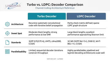
Both families approach the Shannon limit, but they have different operational profiles:
| Feature | Turbo | LDPC |
|---|---|---|
| Architecture | Two parallel SISO decoders | Iterative belief propagation on sparse matrix |
| Sweet spot | Shorter block lengths, lower latency | High throughput, hardware parallelism |
| Standards | 3G/UMTS (R=1/3), 4G LTE, CCSDS deep space | 5G NR, DVB-S2, Wi-Fi, CCSDS TM |
| Parallelizability | Limited | High |
ETSI TS 125.212 specifies UMTS turbo coding as a Parallel Concatenated Convolutional Code (PCCC) with two 8-state constituent encoders and an internal interleaver. ETSI TS 136.212 specifies the same architecture for LTE. Lumistar's product line supports LDPC and convolutional/Viterbi decoding, aligning with the dominant standards across aeronautical telemetry and modern wireless systems.
Key Factors That Affect FEC Decoding Proven Performance
Code Rate and Throughput Trade-Off
Code rate is the ratio of data bits to total transmitted bits. Lower code rate = more redundancy = better error correction, but reduced effective data throughput.
IRIG 106-15 Appendix R defines three code rates for AMT LDPC — 1/2, 2/3, and 4/5 — each with corresponding block size options:
| Rate | k (info bits) | n (total bits) |
|---|---|---|
| 1/2 | 1024 | 2048 |
| 1/2 | 4096 | 8192 |
| 2/3 | 1024 | 1536 |
| 2/3 | 4096 | 6144 |
| 4/5 | 1024 | 1280 |
| 4/5 | 4096 | 5120 |
Code rate selection is driven by expected channel Eb/N0 and link margin budget. Over-coding wastes scarce bandwidth. Under-coding risks cliff-effect failures at range extremes or poor aircraft attitudes.
Pre-FEC BER Threshold and Operating Margins
Each decoder type has a characteristic threshold BER above which it cannot recover data. System designers must verify the channel operates within correction margins under worst-case conditions — maximum range, adverse antenna angles, deep fades.
This threshold differs meaningfully between RS, LDPC, and convolutional decoders. Treating them as interchangeable in link budget calculations is a planning error — and the hardware used to implement each decoder compounds those differences in ways that matter at the system level.
Decoder Hardware Implementation
Turbo and LDPC decoders require iterative processing, introducing pipeline latency. In real-time telemetry ground stations, this latency must be bounded and compatible with downstream PCM decommutation timing.
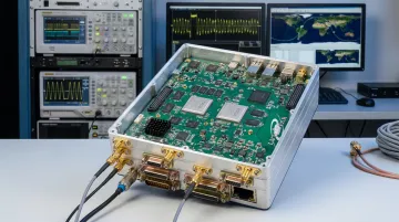
Lumistar implements FEC decoding using FPGA-based architecture across its product lines. The LS-35-R, for example, uses Xilinx Virtex-5 FPGAs for signal processing. The key advantage of FPGA implementation is field upgradeability — FEC capabilities can be added or updated via firmware without hardware replacement, which matters when requirements shift across long programs or when IRIG 106 revisions introduce new code options.
Common Misconceptions About FEC Decoding
"FEC can correct any number of errors if the code is strong enough."
No FEC decoder has unlimited correction capacity. Once pre-FEC BER exceeds the code's correction boundary, post-FEC BER doesn't degrade gracefully — the error floor drops sharply and unpredictably. Engineers who budget link margin assuming FEC will always recover data risk losing entire test events without warning.
"A stronger code always produces a better system."
Higher redundancy reduces effective data rate. A code engineered for the theoretical worst case wastes bandwidth that could carry useful telemetry. The correct code rate is determined by actual expected channel conditions, not by maximizing redundancy.
"Any encoder and decoder of the same code type will interoperate."
Encoder and decoder must match on every parameter, including:
- Code type and code rate
- Generator or parity-check matrix
- Interleaver design
- Block sizes and randomization rules
- Modulation coupling
IRIG 106-15 Appendix R ties all of these to specific LDPC configurations. A mismatch on any one produces complete data loss, not correctable errors. This is a recurring integration failure in multi-vendor flight test programs where airborne and ground-side equipment come from different suppliers.
Frequently Asked Questions
What is FEC (forward error correction)?
FEC is a technique where the transmitter adds redundant bits to data before transmission, allowing the receiver to detect and correct channel-introduced errors without requesting retransmission. Per ITU-T X.141, FEC corrects received data errors without requiring a feedback channel.
What is a FEC decoder?
A FEC decoder is the hardware or software component at the receiver that processes an incoming encoded bitstream. It applies the appropriate decoding algorithm — Viterbi, belief propagation, Berlekamp-Massey, and others — and outputs the corrected original data.
How does FEC decoding work?
The decoder uses parity or reliability information embedded in the received signal to identify likely error positions, applies its decoding algorithm to determine correct bit values, and outputs recovered data, while monitoring pre- and post-FEC BER to confirm operation within the decoder's correction boundary.
What is the difference between FEC and retransmission?
FEC corrects errors proactively using redundancy already present in the transmitted signal — no feedback channel required. ARQ retransmission detects errors and asks the sender to resend the data, requiring a bidirectional link. Flight test telemetry downlinks use FEC precisely because no return channel exists.
How do turbo decoders compare to LDPC decoders?
Both achieve near-Shannon-limit performance, but serve different use cases. Turbo decoders perform better at shorter block lengths and are the standard in 3G/4G LTE and CCSDS deep space applications. LDPC decoders are more parallelizable and dominate high-throughput applications including 5G NR and DVB-S2.
What is coding gain in FEC?
Coding gain is the reduction in required Eb/N0 that an FEC system delivers to achieve the same bit error rate as an uncoded transmission. Higher coding gain means maintaining data integrity at lower received signal power, which translates directly to extended range or reduced transmit power requirements in flight test link budgets.