Key Takeaways
- IQ stands for In-phase and Quadrature — two orthogonal signal components that together capture the full amplitude and phase information of any RF signal.
- An IQ downconverter uses two mixers with a 90° LO phase offset to translate RF directly to baseband, eliminating the image frequency problem of single-mixer designs.
- This direct-conversion architecture reduces hardware complexity and supports compact, software-defined receivers suited for flight test telemetry ground stations.
- Key design challenges (DC offset, IQ imbalance, and second-order distortion) are all manageable through modern DSP calibration techniques.
What Is an IQ Downconverter Receiver?
An IQ downconverter receiver is a radio front-end architecture that translates a received RF signal down to baseband using two parallel signal paths. One path processes the In-phase (I) component; the other processes the Quadrature (Q) component. A local oscillator drives both paths simultaneously, with a precise 90° phase offset between them.
The names I and Q have direct physical meaning. The I path carries the cosine-referenced component of the signal; the Q path carries the sine-referenced component. Together, they encode the full amplitude and phase of the received signal — the real and imaginary parts of what engineers call the complex baseband representation. Neither path alone is sufficient; both are required to reconstruct the original signal without ambiguity.
Why Complex Downconversion Matters
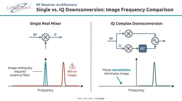
Mixing an RF signal with a single real sinusoid produces both sum and difference frequencies, creating an image-frequency ambiguity that requires additional filtering to resolve. Mixing with a complex sinusoid — cosine plus j·sine — performs a one-sided spectral shift, moving the desired signal band directly to DC while mathematically canceling the unwanted mirror image. No image filter required. That is the core advantage of the IQ approach over a basic single-mixer downconverter: image rejection through phase cancellation rather than brute-force filtering.
The architecture goes by several names in the literature. Behzad Razavi's foundational IEEE paper uses direct conversion, zero-IF, and homodyne conversion as equivalent terms. Texas Instruments uses "direct down-conversion." All refer to the same fundamental operation: converting the RF signal in a single step directly to complex baseband.
Common naming variants include:
- Direct conversion — emphasizes the single-step RF-to-baseband translation
- Zero-IF — describes the zero intermediate frequency result
- Homodyne — classical term for same-frequency mixing
- Direct down-conversion — Texas Instruments' preferred terminology
How IQ Downconversion Works: The Signal Chain
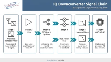
A well-designed IQ downconverter follows a consistent signal chain from antenna to digital output. Each stage has a defined role.
Front-End: Filter and Amplify
The received RF signal enters through the antenna, passes through a preselect bandpass filter to suppress out-of-band interference, then reaches the Low Noise Amplifier (LNA). The LNA boosts signal level while adding as little noise as possible; its noise figure sets the sensitivity floor for the entire receiver chain.
Lumistar's LS-25-D2 downconverter achieves a noise figure of 6 dB typical / 8 dB maximum, while the LS-28-DRSM series reaches 4 dB, performance consistent with demanding flight test telemetry applications.
Quadrature LO Generation
A single Local Oscillator (LO), tuned to the carrier frequency of interest, feeds a 90° hybrid splitter. As documented in Marki Microwave's quadrature hybrid coupler data, this component produces two outputs of equal amplitude with exactly 90° phase difference between them. One output (0°, cosine) drives the I-path mixer; the other (90°, sine) drives the Q-path mixer.
Dual Mixing and Lowpass Filtering
The amplified RF signal is split into two equal-power paths via a 0° power divider. Each path feeds one mixer:
- I mixer multiplies the RF by the cosine LO → produces the I baseband component
- Q mixer multiplies the RF by the sine LO → produces the Q baseband component
ADI's CN-0374 circuit note shows that after filtering the sum term, the outputs reduce to:
- I = (A/2) cos(φ_RF − φ_LO)
- Q = (A/2) sin(φ_RF − φ_LO)
Each path then passes through a lowpass filter that removes the double-frequency mixing product (2×RF) and defines channel bandwidth. These filters determine selectivity.
ADC and DSP
The filtered I and Q signals are digitized by matched ADCs. Downstream FPGA or DSP blocks perform demodulation, DC offset removal, and IQ imbalance compensation. TI's direct down-conversion reference design validates this architecture in production hardware, combining the TRF3711 IQ demodulator, ADS5282 ADCs, and FPGA-based correction blocks. Understanding each stage's contribution makes it easier to evaluate where a given downconverter design may introduce performance trade-offs.
IQ Downconverters vs. Superheterodyne Receivers
The core tradeoff between these two architectures comes down to where filtering happens — in hardware stages or in DSP. A superheterodyne receiver routes the RF signal through one or more intermediate frequency (IF) stages before demodulation, using physical IF filters for selectivity. That approach works, but it adds mixing stages, components, and bulk.
Here's how the two architectures compare across dimensions that matter for flight test applications:
| Parameter | IQ Direct Conversion | Superheterodyne |
|---|---|---|
| Conversion stages | Single (RF → baseband) | Multiple (RF → IF → baseband) |
| Image rejection | Phase cancellation (IQ paths) | Physical IF filter |
| ADC clock requirement | Lower (e.g., 200 MHz for 40 MHz signal) | Higher (e.g., 400 MHz for same signal) |
| Form factor | Compact, fewer components | Larger, more stages |
| Primary impairment | IQ imbalance, DC offset | Image frequency leakage |
| SDR/multi-standard flexibility | High | Lower |
The ADC clocking advantage deserves attention: TI's direct down-conversion application note shows that a 40 MHz composite signal requires only 200 MHz ADC clocking in a direct conversion design versus 400 MHz for an equivalent real heterodyne approach — a 2× efficiency gain.
When to choose which:
- Superheterodyne remains advantageous where extremely high dynamic range or very narrow IF filtering is non-negotiable
- IQ direct conversion is the better choice when SWaP (Size, Weight, and Power) constraints are critical, when multi-standard reception is needed, or when DSP can handle residual impairments — the standard approach in current FPGA- and DSP-based ground station designs
Key Design Challenges in IQ Downconverter Receivers
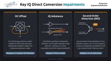
Direct conversion receivers trade IF filtering for baseband complexity — and three specific impairments demand deliberate mitigation before they degrade system performance.
DC Offset
When the LO and RF operate at the same frequency, LO energy leaks through mixer port isolation and self-mixes, producing a DC component at the baseband output. This DC offset can saturate downstream amplifiers and erode ADC dynamic range. ADI quantifies the impact: a 10 mV DC offset can reduce ADC dynamic range by 0.9 dB in a DC-coupled signal chain.
Mitigation options include AC coupling, on-chip DC offset calibration circuits, and DSP-based tracking algorithms. TI's reference design updates I/Q DC-offset correction values every 1.067 ms — treating calibration as a continuous process rather than a one-time factory setting.
IQ Imbalance
Perfect quadrature mixing requires exactly 90° phase separation and identical gain in both paths across the full signal bandwidth. Analog hardware cannot achieve this perfectly. Amplitude mismatch and phase error between the I and Q arms cause image leakage, constellation distortion, and degraded Error Vector Magnitude (EVM) — most damaging for higher-order modulation schemes.
The performance gap is measurable. TI reports EVM improvement from −35.66 dB to −51.4 dB after applying FPGA-based IQ correction. The ADL5380 IQ demodulator from ADI specifies 0.07 dB amplitude balance and 0.2° phase balance at 900 MHz — a strong hardware foundation that DSP correction then refines to close remaining error.
Second-Order Distortion (IM2)
Unlike superheterodyne designs — where third-order intermodulation (IIP3) is the dominant linearity concern — direct conversion receivers are vulnerable to second-order distortion. The IM2 product of two interferers falls directly at baseband, in-band, rather than at an out-of-band IF where filtering removes it. A strong single interferer can also self-mix to produce a DC-like disturbance.
This makes IIP2 a critical specification for direct conversion designs. ADI reports that IIP2 optimization can reduce an IM2 spur by approximately 20 dB, bringing it to −81.37 dBc — enough headroom to receive weaker signals alongside strong co-channel interferers without corruption.
IQ Downconverters in Aerospace and Flight Test Telemetry
Flight test telemetry imposes specific demands on receiver hardware. Aircraft and test vehicles transmit wideband RF signals across the aeronautical telemetry bands defined by IRIG 106 — including L-band (1435–1540 MHz, 1710–1850 MHz), S-band (2200–2400 MHz), and C-band (4400–4950 MHz). Ground stations must capture these signals in real time, across dynamic flight conditions, with no tolerance for data gaps.
The IQ direct-conversion architecture fits this environment well for several reasons:
- Single-stage downconversion reduces component count and failure modes
- Wide instantaneous bandwidth supports capture of modern waveforms including SOQPSK-TG, FQPSK-JR, and ARTM CPM as specified in IRIG 106 Chapter 2
- Software-defined baseband allows firmware updates as standards evolve — without hardware replacement
- Compact form factor enables the industry shift from large rack-mounted systems toward portable and hand-held configurations
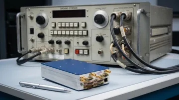
These architectural advantages translate directly into measurable size and power reductions. Less than two decades ago, a typical flight test telemetry ground station stood 8 feet tall, weighed 250 kg, and consumed thousands of watts. Lumistar's current LS-28-DRSM series modules measure 6.00" × 4.00" × 1.67" — under 1 kg, running at approximately 40 watts typical — delivering the same core functionality at a fraction of the footprint.
Lumistar's receiver products are designed and manufactured in the USA for aeronautical flight test telemetry, supporting IRIG 106 Class I and Class II waveform standards across 200 MHz to 6 GHz. The LS-29-R2 RF recording and playback system extends this capability with up to 200 MHz instantaneous system bandwidth and 120 dB instantaneous dynamic range, capturing the full signal environment for post-mission analysis.
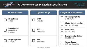
Choosing the Right IQ Downconverter: Key Specifications to Evaluate
When evaluating an IQ downconverter for telemetry or wireless system applications, focus on these specification categories:
RF Performance
- Noise figure — determines receiver sensitivity and minimum detectable signal; lower is better. Telemetry receiver examples range from 3.5 dB (Quasonix RDMS Gen 3) to better than 12 dB depending on design
- Instantaneous bandwidth — sets the maximum signal bandwidth captured in one acquisition; the ADI LTC5585 supports 300 MHz RF signals with I and Q outputs each 150 MHz wide as one benchmark
- Image rejection — determined by IQ amplitude and phase balance; the ADL5380 achieves 0.07 dB / 0.2° balance at 900 MHz before digital correction
RF performance specs define the sensitivity ceiling of your receiver. Dynamic range specs determine how well it holds up under real-world signal conditions.
Dynamic Range
- SFDR (Spurious-Free Dynamic Range) — quantifies the effect of spurious signals on usable dynamic range
- IIP2 — critical for direct conversion; TI's TRF3711 specifies 60 dBm out-of-band IIP2 at 2400 MHz
- IIP3 — ADI's ADL5380 achieves 29.7 dBm IP3 at 900 MHz; TI's TRF3711 specifies 24 dBm out-of-band
Once the RF and dynamic range requirements are confirmed, deployment context shapes the remaining decisions.
Integration and Practical Considerations
- ADC sampling rate — must meet Nyquist for the full IQ bandwidth; direct conversion requires half the clock rate of an equivalent real heterodyne design
- Digital output interface — I/Q data format compatibility with downstream FPGA or DSP
- Form factor — rack-mount, board-level (PCI), modular brick, or portable enclosure depending on deployment
- Environmental rating — operating temperature range, vibration tolerance, and ingress protection (IP rating) for field-deployed systems; MIL-STD-810H covers shock, vibration, and temperature extremes for qualification
- Vendor support — evaluate firmware upgrade paths, post-delivery technical support availability, and calibration data access; these factors become critical for defense programs with 10–20 year operational lifespans
Frequently Asked Questions
What does IQ stand for in IQ downconverter receivers?
IQ stands for In-phase and Quadrature — the two orthogonal components of a complex baseband signal. Together, they capture the full amplitude and phase information of the received RF signal, enabling complete signal reconstruction without ambiguity.
What does the mixer do in a superheterodyne receiver?
In a superheterodyne receiver, the mixer multiplies the incoming RF signal with a local oscillator signal, producing sum and difference frequency outputs. This translates the desired signal down to a fixed intermediate frequency (IF) where filtering and amplification are more practical.
How does an RF upconverter work?
An RF upconverter performs the reverse of downconversion. It mixes a baseband or IF signal with a local oscillator to shift it up to a higher RF frequency for transmission, generating upper and lower sideband products in the process.
What is image rejection and why does it matter in IQ downconverters?
Image rejection is a receiver's ability to suppress signals at the image frequency — the frequency that produces the same output as the desired signal. In IQ downconverters, image rejection is achieved through phase cancellation between the I and Q paths rather than filtering, with performance determined by how closely matched those two paths are in amplitude and phase.
What causes IQ imbalance and how can it be corrected?
IQ imbalance stems from manufacturing tolerances that produce unequal gain or imprecise 90° phase separation between the I and Q paths. Digital calibration algorithms in the DSP or FPGA measure these amplitude and phase errors and apply compensating corrections in real time.
How is an IQ downconverter receiver used in telemetry ground stations?
In flight test telemetry, IQ downconverter receivers translate RF signals from aircraft under test directly to complex baseband for demodulation and data recovery. This enables compact ground station designs (including portable and hand-held configurations) that receive, process, and record high-bandwidth telemetry data in compliance with IRIG 106 standards.