Introduction
In any radio telemetry system, the receiver is the ground-side component responsible for capturing RF signals from an airborne vehicle and converting raw transmissions into usable engineering data. Without it, sensor readings — structural loads, engine temperatures, avionics states — never reach the engineers on the ground.
Despite this central role, the receiver's internal workings are often treated as a black box. Program engineers specify frequency bands and sensitivity figures without understanding the signal chain behind reliable data recovery.
A poorly specified or misconfigured receiver introduces errors that propagate through every downstream system — from bit synchronizers to decommutators. Knowing how the receiver works is how you avoid those problems before they reach the data.
This guide breaks down what a telemetry receiver is, how it processes an incoming RF signal step by step, what form factors exist, and which specifications actually matter when selecting one for a flight test program.
Key Takeaways
- A telemetry receiver captures modulated RF signals from an airborne transmitter and outputs a synchronized digital bitstream for downstream processing
- The signal chain runs through RF amplification, downconversion, demodulation, and bit synchronization — then passes to a frame synchronizer
- Receivers come in fixed rack-mounted, portable/mobile, and firmware-flexible modular form factors
- Key specs: frequency range, noise figure, 120 dB dynamic range, supported modulation types (PCM/FM, SOQPSK-TG, ARTM CPM), and IRIG 106 compliance
- The receiver is the first processing stage in any ground station; every downstream data quality limit traces back to it
What Is a Telemetry Receiver?
A telemetry receiver is the ground-station hardware that detects, amplifies, and demodulates a modulated RF signal originating from an airborne or remote transmitter. The "radio" in "radio telemetry" refers to the RF carrier used to transport data — the receiver's job is to recover the embedded digital bitstream from that carrier.
The Operational Gap It Fills
Sensors aboard a test aircraft produce continuous measurements: temperature, pressure, vibration, structural loads, avionics bus states. None of that data can be wired to the ground during flight. The airborne transmitter encodes it and broadcasts via RF; the receiver is the first point at which the ground system can capture and begin interpreting it.
A few important clarifications about what a telemetry receiver is not:
- One-way only — it receives signals but does not transmit responses to the aircraft
- Purpose-built, not general-purpose — unlike an RF scanner, it is designed specifically for telemetry signal formats
- Separate from the antenna — the antenna is an external device that feeds signal into the receiver's front end
- Upstream of processing — frame synchronizers and decommutators are distinct downstream stages
Why Purpose-Built Hardware Still Matters
General-purpose software-defined radio (SDR) hardware exists, but it doesn't replace a dedicated telemetry receiver for most flight test programs. IRIG 106 — the governing U.S. standard for aeronautical telemetry, maintained by the Range Commanders Council — sets specific requirements for receiver performance including local oscillator accuracy, spurious rejection (60 dB minimum), and phase noise.
Meeting those requirements under high-dynamic conditions — fast-moving aircraft, multipath fading, signal dropout — demands purpose-built hardware with validated performance characteristics.
Lumistar's receivers, for example, hold IRIG 106 Chapter 4 Class I and Class II compliance, covering demodulation accuracy across PCM/FM, SOQPSK-TG, and ARTM CPM formats at data rates up to 60 Mbps.
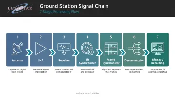
The Ground Station Chain
The receiver sits in a defined processing sequence. Each stage refines the signal, and errors introduced at the receiver propagate through every subsequent step — which is why its performance specification matters so much.
- Antenna — captures the RF signal from the airborne transmitter
- LNA (Low-Noise Amplifier) — boosts weak signal before it degrades further
- Receiver — detects, demodulates, and outputs a clean bitstream
- Bit Synchronizer — recovers the clock and aligns the bit boundaries
- Frame Synchronizer — identifies the data frame structure within the bitstream
- Decommutator — separates individual parameters from the multiplexed stream
- Display/Recording — presents and archives the engineering data
How Does a Telemetry Receiver Work?
A telemetry receiver operates through a sequential signal processing chain. Each stage refines the incoming RF signal until a clean, usable digital bitstream emerges.
RF Front End and Downconversion
The process begins when the antenna delivers a weak, modulated RF signal (typically in L-band or S-band for aeronautical telemetry) to the receiver's RF front end. The first internal stage amplifies this signal while introducing minimal additional noise. Sensitivity established here sets the noise floor for the entire chain.
From there, the amplified RF signal mixes with a locally generated carrier to shift it down to an intermediate frequency (IF) that's easier to filter and process. Lumistar's receivers downconvert to a 70 MHz IF — shared across the LS-28-DRSM, LS-35-R, and LS-25-D2 product lines — and tune across wide frequency ranges simply by adjusting the local oscillator, with no hardware changes required.
IRIG 106-24 Chapter 2 requires local oscillator conversion accuracy within ±0.001% of the indicated tuned frequency and spurious rejection of at least 60 dB referenced to the desired signal from 150 kHz to 10 GHz.
Demodulation
With the signal at IF, the demodulator reverses the modulation scheme used by the airborne transmitter to recover the underlying bitstream. IRIG 106-24 defines three standard modulation types for aeronautical telemetry:
| Modulation | Description | Spectral Efficiency |
|---|---|---|
| PCM/FM | Partial-response CPM used since the 1970s | Standard |
| SOQPSK-TG | Shaped offset QPSK, modulation index 0.5 | Higher than PCM/FM |
| ARTM CPM | Quaternary alphabet, two alternating modulation indexes | Highest |
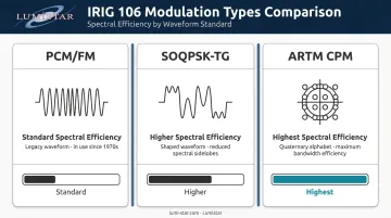
The receiver must support the specific scheme used on the airborne side. Lumistar's LS-28-DRSM series handles this through firmware-based demodulation personalities (PCM/FM, SOQPSK, Multi-H CPM, BPSK, QPSK, and more) selectable without hardware changes.
Bit Synchronization and Output
Once demodulated, the raw output is still an unsynchronized analog waveform. The bit synchronizer recovers clock timing and aligns each data bit to a consistent reference, producing a clean stream of ones and zeros.
Per IRIG 106-24 Chapter 4, a compliant bit synchronizer must:
- Acquire sync within 1,000 bits for NRZ codes at BER 1×10⁻³
- Maintain synchronization at BER 1×10⁻⁵
- Deliver output clock jitter below 10% of the bit period peak-to-peak
Lumistar integrates bit synchronization directly into several receiver units. The LS-28-DRSM series provides three independent bit sync outputs (CH1, CH2, and Combined) simultaneously via TTL and differential RS-422.
The synchronized bitstream then passes to a frame synchronizer, which uses the frame sync word structure established by the airborne commutator to separate multiplexed sensor data back into individual measurement channels.
Types of Telemetry Receivers
Fixed and Rack-Mounted Receivers
Rack-mounted units are the backbone of permanent ground station infrastructure at test ranges and airfields. They offer the highest performance in sensitivity, dynamic range, and channel capacity, and integrate into standard 19-inch rack systems alongside other processing hardware.
Lumistar's rack-mounted options include:
- LS-24-R1/R2/R4 — 1U to 4U rackmount receivers holding 2–4 modular cards
- LS-28-DRS / LS-28-QRS — 4U dual and quad receiving systems with combiners, displays, and all TM demodulations
- LS-84-R4 — complete TM system from RF reception to data display and archiving
Portable and Mobile Receivers
Portable units trade some channel capacity for deployability — used in mobile range operations, chase aircraft, or field test events where permanent infrastructure doesn't exist.
The engineering challenge here is SWaP (size, weight, and power). Lumistar's engineering response is concrete: where traditional ground stations occupied 8-foot racks weighing 250 kg and consuming thousands of watts, the LS-28-DRSM modular unit measures 6.00" × 4.00" × 1.67", weighs under 1 kg (0.95 kg), and draws 40 watts typical.
The LS-28-DRSM-P1 packages this into an IP-67 lunchbox case weighing roughly 15–16 lbs complete — compact enough to carry aboard a chase aircraft and stow in an overhead bin.
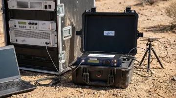
That portability advantage extends to how the hardware adapts over time — without replacing physical components.
Firmware-Flexible Modular Receivers
The LS-28-DRSM series uses a firmware-based personality architecture: modulation support, signal processing modes, and functional configurations are all controlled via firmware rather than dedicated hardware circuits. New demodulation formats or DSP algorithm improvements deploy via firmware update over TCP/IP, with no hardware swap and no return to factory.
This means a single hardware platform can be reconfigured as mission requirements change — a practical advantage for programs that evolve over multi-year test campaigns. Supported waveform personalities on a single unit include PCM/FM, SOQPSK, Multi-H CPM, BPSK, QPSK, OQPSK, AUQPSK, PCM/PM, and analog FM, with data rates up to 60 Mbps.
Where Telemetry Receivers Fit in Aeronautical Flight Test
The receiver sits immediately after the antenna system in any ground station architecture. Its output quality directly determines the ceiling for all downstream processing — a receiver with insufficient sensitivity or the wrong modulation mode configured will produce bit errors that no frame synchronizer can correct.
Operational Environments
Telemetry receivers operate across a range of environments:
- Fixed test range facilities — such as Edwards AFB's 5790 TM Site, where ground engineers monitor test aircraft data in real time from the Ridley Mission Control Center
- Mobile ground stations — deployed for developmental test events at off-range locations
- Airborne relay stations — chase aircraft equipped with airborne receivers like Lumistar's LS-26 Series capture signals from test vehicles and relay them onward
- Retransmission stations — Lumistar's LS-96-M2 range retransmission systems bridge line-of-sight gaps by demodulating and re-transmitting signals over distances of 4 miles or more
Frequency Bands and IRIG 106 Compliance
According to NTIA spectrum allocation records, aeronautical mobile telemetry in the U.S. primarily uses:
- L-band: 1435–1535 MHz
- S-band: 2200–2290 MHz, 2310–2390 MHz, and 2390–2395 MHz
Receiver hardware used in flight test must be designed and validated for operation within these NTIA-allocated bands. IRIG 106 governs the RF link standards that apply across all of these environments.
Matching the Receiver to the Program
Selecting the right receiver requires matching frequency coverage, modulation support, and sensitivity to the specific test program's link budget, vehicle trajectory, and data rate requirements. Lumistar's product line addresses this range of requirements directly, spanning individual receiver cards through complete integrated ground station systems. For programs with complex link geometries or multi-environment deployments, their engineering team provides configuration support, BER troubleshooting, and system integration guidance.
Conclusion
A telemetry receiver is an active signal processing system. Its internal chain — RF front end, downconversion to IF, demodulation, bit synchronization — determines whether a ground station captures clean engineering data or loses it to noise and timing errors.
Engineers who understand these stages can make more precise decisions at every level of ground station design:
- Specify sensitivity requirements accurately before procurement
- Diagnose bit error rate issues in the field rather than blaming the test vehicle
- Configure the correct demodulation mode from the start, not after troubleshooting
That understanding also informs broader architecture decisions: whether to use integrated versus modular receiver configurations, and whether a firmware-flexible platform can consolidate multiple single-purpose units. Lumistar's modular receiver line is built around exactly this principle, using firmware-selectable personalities so a single hardware platform handles tasks that once required separate boxes.
Frequently Asked Questions
What is a telemetry receiver?
A telemetry receiver is ground-based hardware that captures modulated RF signals from a remote transmitter (such as one aboard a test aircraft), amplifies and demodulates the signal, and outputs a synchronized digital bitstream for a frame synchronizer and decommutator to process into individual sensor measurement channels.
What are telemetry radios?
"Telemetry radios" refers to the RF hardware on both ends of the data link: the airborne transmitter that encodes and broadcasts sensor data, and the ground receiver that captures and decodes it. Unlike two-way communication radios, telemetry links are one-directional and optimized for data fidelity.
What can telemetry detect?
A telemetry system can transmit any parameter a sensor can measure and digitize. In aeronautical flight test, that includes structural loads, temperature, acceleration, avionics bus data, and GPS position, among others. The receiver itself doesn't detect these parameters; it delivers the encoded data stream that represents them.
What is the difference between a telemetry transmitter and a telemetry receiver?
The transmitter is the airborne unit that encodes sensor data, modulates it onto an RF carrier, and broadcasts it. The receiver is the ground-based unit that captures that broadcast, demodulates it, and recovers the digital bitstream. Both must be matched in frequency and modulation scheme to function as a one-way RF data link.
What frequency bands do aeronautical telemetry receivers operate on?
Aeronautical telemetry in the U.S. primarily uses L-band (1435–1535 MHz) and S-band (2200–2395 MHz), as allocated by the NTIA and defined by IRIG 106. Receivers must be validated within these bands to ensure interference-free operation and range interoperability.