A BER of 1×10⁻⁶ means one bit in every million arrives corrupted. Whether that's acceptable depends entirely on your application and system specification. Getting to that number accurately, though, requires the right equipment, a valid test setup, and a clear understanding of what you're actually measuring.
This guide covers the tools you need, three practical measurement methods, the BER formula with worked examples, and how to interpret results without drawing the wrong conclusions.
Key Takeaways
- BER formula: Number of bit errors ÷ total bits transmitted — reported as a power of 10 (e.g., 1×10⁻⁶)
- Measurement methods: Dedicated BERT hardware, loopback testing, and live in-service monitoring
- Thresholds vary by link type — fiber post-FEC targets can reach 10⁻¹⁵; telemetry and wireless links typically require ≤10⁻⁶ to ≤10⁻¹⁰
- Pre-FEC vs. post-FEC: Confirm which value your instrument reports — comparing the wrong one invalidates your result
- Sample size matters: Testing too few bits produces statistically meaningless results
What You Need to Measure BER
Getting valid, repeatable BER measurements starts before you touch a test button. The wrong setup — mismatched patterns, unsynchronized clocks, insufficient signal levels — produces numbers that look precise but mask real link problems.
Equipment Required
Core tools for a hardware BERT test:
- Pattern generator (or integrated BERT instrument) — generates the known test bit sequence
- Error detector/counter — compares received bits against the expected pattern and counts mismatches
- **Clock reference or synchronization source** — ensures both ends operate at the same timing
- Digital communications analyzer or oscilloscope — optional, for signal visualization and troubleshooting
- E/O and O/E converters — required for optical links to interface electrical BERT equipment with fiber
In aeronautical telemetry and flight test environments, purpose-built ground station equipment often eliminates the need for separate BERT instruments . Lumistar's telemetry ground stations — including the LS-28-DRSM series and the LS-18-P1 portable system — include integrated BER readers, PRN pattern generators, and loopback test capabilities compliant with IRIG 106 requirements. The LS-45 series bit synchronizers add built-in self-test (BIT) with internal BER measurement covering more than 90% of components on power-up.
Preconditions and Setup
Before starting any BER measurement:
- Confirm link synchronization — the receiver must have acquired and locked onto the incoming signal
- Load matching test patterns — both transmitter and receiver must use the same pattern type and length
- Verify impedance matching and signal levels — connector and cable mismatches introduce errors that have nothing to do with the link under test
- Calculate your minimum sample size — this is where most BER tests fail silently
That last point deserves attention. Keysight's BER confidence guidance documents the standard formula for zero-error tests:
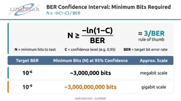
N ≥ −ln(1 − C) / BER
At 95% confidence, this simplifies to roughly 3 / BER bits. Practical implications:
| Target BER | Minimum bits (95% confidence) |
|---|---|
| 10⁻⁶ | ~3,000,000 bits |
| 10⁻⁹ | ~3,000,000,000 bits |
Zero errors in a short run tells you the link is probably good — not that it's perfect. The confidence level depends entirely on how many bits you actually tested.
Methods to Measure BER
The right method depends on whether you can access both ends of the link, whether the system can be taken out of service, and what test equipment is available.
Method 1: Dedicated Hardware BERT Testing
A standalone BERT instrument generates a known test pattern at one end (typically PRBS sequences defined in ITU-T O.150/O.151/O.153) and compares the received bit stream against the expected pattern, counting every mismatch.
Tools needed: BERT instrument with integrated pattern generator and error detector, clock source, cable or RF connections to the device under test (DUT)
Steps:
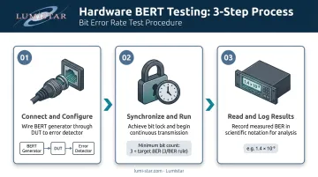
- Connect the BERT pattern generator output to the DUT input; connect the DUT output to the BERT error detector input. Configure both sides to the same test pattern and data rate.
- Allow the link to synchronize and achieve pattern lock, then start the test run. Do not record results until a statistically sufficient number of bits has been transmitted (use the 3/BER rule above).
- Read the BER result displayed in scientific notation or E-notation (for example, 2.5E-06) and log it alongside signal level, SNR, and link conditions for traceability.
Pros: Highest accuracy, most repeatable, direct error counting Cons: Requires test access to both ends; system must be taken out of service
Method 2: Loopback BER Testing
A single BERT instrument operates at one end while a loopback adapter at the far end returns the signal back to the same instrument. No second technician or instrument is needed at the remote site.
Tools needed: BERT instrument, loopback adapter (electrical or optical), access to the far-end port
Steps:
- Install the loopback at the remote end (hardware loopback, software loopback, or line loopback depending on the equipment). Configure the BERT to send and receive the same pattern.
- Run the test for sufficient duration. Monitor for pattern lock loss throughout — a drop in lock itself indicates a link problem, even before you count errors.
For systems designed around this topology, Lumistar's LS-18-M modular system includes one or two BER transmit channels and a dedicated BER receive channel, supporting PN3 through PN23 patterns at bit rates from 1 kbps to 50 Mbps — useful when a portable, single-ended test solution is needed in the field.
Pros: Single-ended — no remote technician or instrument needed; practical for field testing Cons: Measures round-trip BER, which can hide direction-specific impairments
Method 3: Live In-Service BER Monitoring
Rather than interrupting the link, this method reads BER directly from the operational equipment's built-in performance monitoring during normal operation. Sources include FEC counters, receiver status registers, and telemetry processor outputs.
Tools needed: Operational receiver or ground station with built-in BER monitoring; access to the equipment management console or IRIG 106-compliant telemetry processor output
Steps:
- Access the performance monitoring interface and navigate to the BER or error rate display. Confirm whether the value shown is pre-FEC (uncorrected) or post-FEC (corrected) — this distinction is critical and is covered in the next section.
- Log BER readings over a representative operating period. Correlate with received signal level, Eb/N0, or SNR to build a trend picture. A single snapshot is rarely actionable.
Note for aeronautical telemetry: IRIG 106-24 Chapter 2 defines a standardized Data Quality Metric (DQM) framework for estimating bit error probability at the receiver/demodulator and transporting that quality estimate alongside received telemetry data.
Pros: Non-intrusive, continuous monitoring without service interruption Cons: Accuracy depends on the quality of built-in monitoring; does not replace BERT qualification testing
How to Calculate BER: Formula and Examples
The Formula
BER = Number of Bit Errors ÷ Total Number of Bits Transmitted
The result is a dimensionless ratio, expressed in scientific notation.
Worked example: A transmitter sends 10,000,000 bits. The receiver detects 25 errors.
BER = 25 ÷ 10,000,000 = 2.5×10⁻⁶ (displayed on analyzers as 2.5E-06)
Pre-FEC vs. Post-FEC BER
Modern digital links almost always include Forward Error Correction (FEC). This creates two distinct BER values:
- Pre-FEC BER (transmission BER): Errors present in the received bit stream before the FEC decoder corrects them. This reflects raw channel quality.
- Post-FEC BER (information BER): Errors remaining after FEC correction. This reflects delivered data quality.
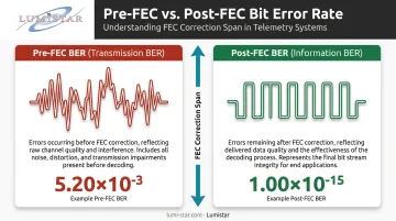
Comparing them reveals FEC effectiveness. ITU-T G.975.1 documents FEC examples for high bit-rate DWDM systems where a pre-FEC input BER of 5.20×10⁻³ maps to a post-FEC output BER of 1.00×10⁻¹⁵ using RS(255,239)/CSOC coding — a correction span of over 12 orders of magnitude.
BER and Eb/N0
BER is directly tied to Eb/N0 — the ratio of energy per bit to noise power spectral density. Two key rules apply across all link types:
- Higher Eb/N0 → lower BER (better signal-to-noise margin)
- Different modulation schemes produce different BER curves at the same Eb/N0
BPSK is more noise-tolerant than QPSK or 8PSK at equivalent Eb/N0. For aeronautical telemetry, IRIG 106-24 Table A-5 provides SOQPSK-TG benchmarks:
| Target BER | Required Eb/N0 |
|---|---|
| 10⁻³ | ~8.5 dB |
| 10⁻⁵ | ~11.5–12 dB |
BER vs. Eb/N0 curves for common modulation schemes are covered in depth in Proakis and Salehi's Digital Communications (5th ed.).
How to Interpret BER Results
A BER number only means something in context. Misreading results means either hardening a link that doesn't need it, or accepting a degraded link that will cause data loss once operational.
Acceptable / Normal BER
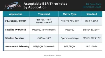
"Acceptable" is defined by the applicable standard and system specification, not by a universal number. Key reference points by application:
| Application | Threshold | Metric type | Standard |
|---|---|---|---|
| Fiber optic / DWDM | Post-FEC: ~10⁻¹⁵; Pre-FEC: ~5×10⁻³ | Pre/post-FEC pair | ITU-T G.975.1 |
| Satellite TV (DVB-S2) | <1 uncorrected error-event per hour at 5 Mbit/s | Post-FEC service metric | ETSI EN 302 307-1 |
| Wireless backhaul | ≤10⁻⁶ to ≤10⁻¹⁰ at declared receiver signal levels | Receiver conformance | ETSI EN 302 217-2 |
| Aeronautical telemetry | BEP/DQM framework; no single universal threshold | BEP estimated at demodulator | IRIG 106-24 Ch. 2 |
Action: If BER is at or below your specified threshold, document the result and continue normal operations.
Minor / Elevated BER
BER that is one to two orders of magnitude above your normal floor — but not yet out of spec — is a yellow-zone indicator. Likely causes: increased noise, minor interference, connector wear, or marginal link budget.
Next steps: Check received signal level and SNR at the receiver. Inspect physical connections and antenna alignment. Retest after adjustments, then monitor the trend over time before drawing conclusions.
Out-of-Spec / High BER
BER approaching 0.5 (50%) means the link is delivering essentially random data. High BER indicates excessive noise, severe interference, excessive attenuation, equipment failure, or synchronization loss.
Action:
- Take the link out of service and run a hardware BERT test to isolate the fault
- Check every component in the signal chain: RF path, cabling, connectors, modulator/demodulator settings
- Verify that modulation scheme and data rate are configured identically at both ends
Common Errors and Best Practices in BER Measurement
The Four Most Consequential Mistakes
1. Insufficient sample size
Observing zero errors over a short run does not prove excellent BER — it may simply mean you haven't transmitted enough bits to encounter an error at the expected rate. Apply the formula N ≥ −ln(1−C) / BER and don't declare a result until the required bit count is met.
2. Confusing pre-FEC and post-FEC readings
Confirm which value the instrument is reporting before comparing it to a specification threshold. A pre-FEC BER of 10⁻³ on a fiber link may be perfectly healthy with aggressive FEC applied. That same number on a system without FEC represents catastrophic failure — and mixing the two produces false passes on failing links.
3. Wrong test pattern for the system under test
Using an all-zeros pattern on a system with AMI coding violates the coding rules and produces invalid results. Match the test pattern to the system: ITU-T O.150/O.151/O.153 define the standard PRBS sequence families (the 511-bit pattern in O.153 corresponds to PRBS-9). For systems requiring configurable PRBS patterns, the Lumistar LS-50-E supports pseudo-random bit sequences from 11 to 25 bits, selectable through its software interface — a practical way to ensure the test pattern matches what the link actually expects.
4. Testing before synchronization is stable
Starting measurement before the link reaches steady-state synchronization inflates the error count with lock-acquisition transients.
Avoiding these mistakes gets you to valid data. The following practices keep you there consistently.
Best Practices Summary
- Allow full synchronization before starting measurement
- Calibrate test equipment before use
- Record all test conditions: data rate, pattern type, signal level, temperature if relevant
- In flight test environments, cross-reference BER with received signal level logs to assess link margin — not just pass/fail
- Treat any zero-error result as a confidence bound, not a guarantee of zero BER
Frequently Asked Questions
How do you measure bit error rate?
BER is measured using a BERT instrument (or built-in receiver monitoring) that compares a known transmitted bit pattern to the received bit stream and counts mismatches. The error count is then divided by the total bits transmitted over the test period to produce the BER ratio.
How do you calculate the bit error rate?
BER = Number of Bit Errors ÷ Total Bits Transmitted, expressed as a dimensionless ratio in scientific notation. For example, 1×10⁻⁶ means one error per million bits transmitted.
What is the standard for BERT testing?
Standards vary by industry: ITU-T G.821/G.826 cover telecom error performance, while the O-series (O.150, O.151, O.153) defines BERT instrumentation and test sequences. For aeronautical telemetry, IRIG Standard 106-24 governs modulation, FEC, and data quality metrics.
What does a high BER mean?
A high BER means a significant proportion of bits are arriving in error — caused by excessive noise, interference, attenuation, or equipment malfunction — resulting in data corruption, packet loss, or complete loss of usable link information.
What is the acceptable BER for my application?
Acceptable BER is application-specific and defined in the system's technical specification. Common reference points: fiber optic links target post-FEC BER around 10⁻¹⁵; wireless backhaul receiver conformance thresholds run ≤10⁻⁶ to ≤10⁻¹⁰ per ETSI EN 302 217-2.
What unit is BER measured in?
BER is dimensionless — it has no units. It is expressed as a plain ratio or in scientific notation (for example, 1×10⁻⁶ or 1.0E-06), representing the probability of a bit error relative to the total bits transmitted.