Introduction
Every time a flight test engineer watches live sensor data stream from an aircraft during a test mission, a modem is doing the critical work. The same is true when a cellular base station handles a voice call, or when a satellite link delivers command telemetry to a remote platform. In each case, the same process is running: digital data encoded onto a carrier wave, transmitted across a physical channel, and decoded back into usable information at the other end.
Most engineers and technicians interact with modulated signals daily. If you can't explain why one modulation scheme outperforms another on a noisy RF link, that gap shows up in poor signal selection, misconfigured hardware, and data quality problems that are hard to diagnose once a test is already underway.
This guide covers how a modem works as a modulation and demodulation device, the major signal techniques in use today, and where this technology matters most. The focus is on aerospace and flight test telemetry environments, where modulation choices have direct consequences for test validity and safety.
Key Takeaways
- A modem (modulator-demodulator) encodes digital data onto a carrier signal for transmission, then decodes a received signal back into usable data.
- Modulation works by varying a carrier wave's amplitude, frequency, or phase to represent binary information.
- Higher-order schemes (such as 16-QAM) deliver more data per symbol but require better signal quality than simpler formats like BPSK or FSK.
- In aerospace telemetry, IRIG 106 defines the modulation standards for flight test ranges: PCM/FM, SOQPSK-TG, and ARTM CPM.
What Is a Modem?
A modem — short for modulator-demodulator — is a device that converts digital data into a form suitable for transmission over a communication channel, then converts the received signal back into its original digital form. Both functions live within a single hardware or software unit.
The reason modems exist is straightforward: digital systems produce binary data that doesn't travel efficiently over most physical channels in raw form. RF spectrum, telephone lines, and coaxial cable all carry analog or modulated waveforms, not raw bitstreams. The modem solves this mismatch by translating data into a waveform the channel can carry, and reversing that translation at the destination.
What a Modem Is Not
Three terms frequently get conflated with "modem," and the distinctions matter:
- Router — directs data packets between network devices; operates at the network layer, not the signal layer
- Transceiver — handles RF transmission and reception at the signal level; may contain modem functions but is broader in scope
- Codec — encodes or decodes audio, video, or data representation; distinct from RF carrier modulation
The modem's specific job is signal-level conversion between digital data and a modulated waveform.
Types of Modems
The core modulation-demodulation principle is consistent across all variants, even as implementation differs significantly:
- Dial-up analog modems (telephone lines)
- DSL and cable modems (broadband)
- Satellite modems (long-path, high-attenuation links)
- Software-defined modems (firmware-configurable waveform processing)
- Telemetry modems (aerospace and flight test environments)
In specialized telemetry hardware, this combined function appears inside products like Lumistar's LS-35-R IF Receiver/Combiner/Modulator. This single board handles multi-mode demodulation (PCM/FM, BPSK, QPSK, SOQPSK, and others) and includes an integrated 70 MHz IF modulator for simulation and BER testing — modulation and demodulation in one unit.
How Does a Modem Work?
A modem operates through a defined sequence: signal preparation, modulation onto a carrier, transmission, reception, and demodulation. Each stage has specific technical requirements that determine overall system performance.
Preparing the Signal
The process begins with a digital bitstream from the source system. The modem's modulator section accepts this data and locks onto a carrier signal (a continuous waveform at a defined frequency) which serves as the vehicle for the information.
The carrier frequency must match the channel's available bandwidth and propagation characteristics. In aeronautical telemetry, the FCC's frequency allocations assign specific bands for flight test use: L-band (1435–1525 MHz), S-band (2310–2395 MHz), and C-band (4400–4940 MHz).
Core Operation: Modulation
During modulation, the modem varies one or more properties of the carrier wave (amplitude, frequency, or phase) in a pattern that encodes binary data. Each variation corresponds to a symbol representing one or more bits.
The performance tradeoff here is direct. According to ITU-R SM.2022-1, in an AWGN-only fixed-link scenario:
| Modulation | Error Target | Required S/N |
|---|---|---|
| FSK | BER 1×10⁻⁵ | ~12.2 dB |
| 4-PSK (QPSK) | SER 1×10⁻⁵ | ~14.5 dB |
| 16-QAM | SER 1×10⁻⁵ | ~20.6 dB |
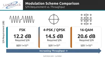
Higher-order schemes pack more bits per symbol, raising throughput — but demand a better signal-to-noise ratio to work reliably. Lower-order schemes are more forgiving in noisy or RF-challenged environments.
Lumistar's demodulator products support this full range, with modulation formats selectable via firmware license rather than fixed at manufacture. The LS-28-DRSM series, for instance, switches between PCM/FM, SOQPSK, Multi-H CPM, BPSK, QPSK, OQPSK, and others through firmware-based personalities — no hardware changes required.
Demodulation: Recovering the Data
Once the modulated signal reaches the receiving end, the demodulator captures it, identifies the carrier, and extracts the pattern of variations to reconstruct the original bitstream, mapping each received symbol back to its corresponding data value.
Accurate demodulation depends on synchronizing with the transmitter's carrier frequency and timing. Phase-locked loops (PLLs) and clock recovery circuits maintain this alignment. Lumistar's bit synchronizer products implement all-digital PLL architectures using FPGA-based signal processing, with programmable loop bandwidths as tight as 0.001% of bit rate and BER performance within 1 dB of theoretical limits for NRZ/RZ signals below 20 Mbps.
Regulation and Error Control
Real channels are imperfect. Received signal strength fluctuates, noise enters the path, and multipath effects distort the waveform. Three mechanisms work together inside the modem to compensate:
- Automatic Gain Control (AGC) — keeps signal level stable as path conditions change; RCC 119-06 notes that the best AGC time constant for data receivers is the fastest available: 0.1 ms
- Forward Error Correction (FEC) — adds redundancy to the data stream so the receiver can reconstruct corrupted bits; Lumistar products support Viterbi decoding (rate 1/2, k=7 and higher), Reed-Solomon, and LDPC per IRIG 106 standards
- Clock synchronization — maintains timing alignment between transmitter and receiver so symbol boundaries are correctly identified
Lumistar's LS-27-M tracking receivers include programmable AGC with five selectable time constants (0.1 to 1,000 ms), while the LS-28-DRSM provides 120 dB of AGC dynamic range across its RF input.
Types of Modulation Techniques
Amplitude and Frequency Modulation
AM (Amplitude Modulation) varies the carrier's amplitude to encode data. It's simple to implement and carries over long distances, but amplitude is exactly what noise tends to corrupt — making AM less suited to high-interference environments.
FM (Frequency Modulation) shifts the carrier's frequency instead. Because noise typically affects amplitude rather than frequency, FM is far more resistant to interference. In flight test telemetry, PCM/FM — where pulse-code-modulated data is frequency-modulated onto an RF carrier — has been the baseline waveform for decades and remains an IRIG 106 standard (ARTM Tier 0).
Phase Shift Keying
Phase modulation encodes data by changing the carrier's phase rather than its amplitude or frequency.
- BPSK (Binary PSK) — two phase states, one bit per symbol; highly robust in poor channel conditions
- QPSK (Quadrature PSK) — four phase states, two bits per symbol; doubles the data rate of BPSK without requiring additional bandwidth
QPSK variants are common in satellite links and telemetry systems where bandwidth efficiency matters and signal quality supports higher-order encoding.
Quadrature Amplitude Modulation (QAM)
QAM combines amplitude and phase variation to pack more bits into each symbol. 16-QAM encodes 4 bits per symbol; 64-QAM encodes 6. This makes QAM the dominant choice in cable internet, LTE, and Wi-Fi where throughput is the priority and the signal environment is controlled. The tradeoff — as the ITU data above shows — is significantly higher S/N requirements compared to PSK at the same error rate target.
Telemetry-Specific Formats: SOQPSK and ARTM CPM
Standard QPSK isn't optimized for the crowded, RF-challenged flight test environment. IRIG 106 Chapter 2 defines two formats specifically engineered for aeronautical telemetry:
- SOQPSK-TG (Shaped Offset QPSK - Telemetry Group) — ARTM Tier 1; a spectrally efficient variant of OQPSK with pulse shaping that reduces out-of-band emissions. Note that SOQPSK-TG and OQPSK are distinct formats and are not interchangeable.
- ARTM CPM (Multi-H Continuous Phase Modulation) — ARTM Tier 2; a continuous-phase waveform designed to minimize spectral occupancy in congested test range environments
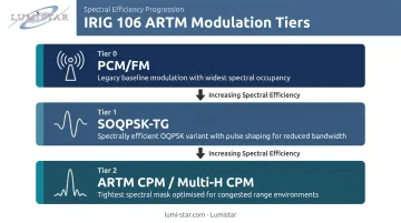
IRIG Appendix A provides direct spectral comparisons of 10 Mbps PCM/FM, SOQPSK-TG, FQPSK-JR, and ARTM CPM, confirming that the modern formats operate within tighter spectral masks than legacy PCM/FM.
For programs that must comply with the full tier stack, Lumistar's LS-18-R1, LS-18-P1, LS-28-DRSM, and LS-35-R each support Tier 0, Tier 1, and Tier 2 formats with IRIG 106 Chapter 4 Class I and Class II compliance across the product line.
Where Modems and Modulation Are Used
Commercial and Broadcast Systems
AM and FM radio, digital television, cable internet, and cellular networks all depend on modulation-demodulation to move voice, video, and data across spectrum-limited channels. The modulation scheme in each case reflects a deliberate tradeoff: FM for broadcast audio because of its noise resistance, QAM variants in cable and LTE because signal quality in those environments supports higher-order encoding.
Satellite and Defense Communications
Satellite uplinks and downlinks use phase and frequency modulation variants to handle long path distances and significant signal attenuation. Military systems apply similar techniques under controlled frequency allocations, with additional security encoding layered on top of the RF modulation.
Aerospace and Flight Test Telemetry
This is where modulation decisions carry the most direct operational consequences. During a flight test, onboard transmitters modulate sensor and measurement data — structural loads, temperatures, pressures, avionics outputs — onto an RF carrier. Ground receiving stations demodulate that signal in real time, giving engineers a live data feed. Signal fidelity directly affects both the safety of the test and the validity of the data.
Lumistar designs and manufactures ground station components specifically for this environment. The LS-28-DRSM series — roughly the size of a hard drive at 6.00" × 4.00" × 1.67" and under 1 kg — delivers the complete RF-to-data chain in a single unit:
- Dual-channel reception across six bands (200 MHz to 6 GHz)
- Multi-mode demodulation
- Three independent bit synchronizers
- IRIG Chapter 10 packet output
- 40–50 watt power draw
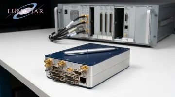
When the LS-28-DRSM series launched in 2017, it represented a significant departure from what flight test ground stations had traditionally required. A typical station once occupied an 8-foot rack, weighed 250 kg, and consumed thousands of watts.
Lumistar's modular architecture brought that same capability down to a hand-held form factor — a practical advantage for mobile deployments, antenna pedestal integration, and airborne re-radiation applications.
Those deployment advantages translate directly to programs at scale. Lumistar was selected by Wichita State University's NIAR to provide the telemetry tracking, receiving, and processing systems for the Kansas Supersonic Transportation Corridor — a 770-nautical-mile supersonic flight test corridor supporting data collection for programs involving Boeing, Lockheed Martin, and others.
Conclusion
A modem's value lies in bridging two fundamentally different signal worlds: the discrete binary data that digital systems produce and the continuous waveforms that physical transmission channels carry. The choice of modulation technique determines how efficiently and reliably that bridge performs.
For engineers working in flight test and aerospace telemetry, that choice has real consequences. Knowing how PCM/FM, SOQPSK-TG, and ARTM CPM each behave under different noise conditions and bandwidth constraints shapes every downstream decision — from hardware selection and link budget planning to diagnosing data quality failures in the field. Lumistar's engineering team applies that same system-level thinking across the full product line, from RF reception through PCM processing and ground station integration.
Frequently Asked Questions
What is the combined device for modulation and demodulation?
A modem (modulator-demodulator) performs both functions. It encodes digital data onto a carrier signal for transmission and decodes the received signal back into its original data form, all within a single hardware or software unit.
What is the difference between modulation and demodulation?
Modulation is the transmit-side process of encoding information onto a carrier wave by varying its amplitude, frequency, or phase. Demodulation is the receive-side process of reading those variations to reconstruct the original data.
What are the most common types of modulation used in communication systems?
AM, FM, PSK variants (BPSK, QPSK), FSK, and QAM are the most widely used. The right choice depends on channel noise, available bandwidth, and required data rate: FM and PSK suit noise-resistant links, while QAM is preferred where high throughput is the priority.
How does a modem differ from a router?
A modem handles signal-level conversion between digital data and a modulated waveform suitable for a transmission channel. A router operates at the network level, directing data packets between devices. They perform distinct functions and are typically separate hardware units.
What modulation formats are used in aerospace telemetry systems?
IRIG 106 defines the standards: PCM/FM (ARTM Tier 0) is the legacy baseline, SOQPSK-TG (Tier 1) provides improved spectral efficiency, and ARTM CPM or Multi-H CPM (Tier 2) is used where spectrum congestion on test ranges demands tighter bandwidth control.
What happens when demodulation fails or produces errors?
Demodulation errors produce bit errors that corrupt sensor readings or create data gaps in the telemetry record — a direct threat to test validity in real-time flight test applications. Forward error correction (FEC) and adequate link margin planning are the primary defenses.