Introduction
Most RF link budgets are tight. QPSK — Quadrature Phase Shift Keying — addresses that constraint directly: it encodes two bits per symbol by selecting one of four carrier phase states, doubling spectral efficiency compared to BPSK without requiring additional bandwidth.
For RF engineers, telemetry system designers, and aerospace/defense professionals, understanding QPSK at an operational level matters. It underpins satellite links, aeronautical telemetry, and wireless communications standards from DVB-S2 to UMTS. In practice, though, its I/Q architecture, demodulation requirements, and variant selection logic are frequently the source of implementation errors.
This article covers QPSK end-to-end: how the modulator and demodulator work, what the waveforms and constellation look like, how key variants differ, and where common implementation mistakes occur.
Key Takeaways
- QPSK encodes 2 bits/symbol using four phase states (π/4, 3π/4, 5π/4, 7π/4), doubling BPSK's spectral efficiency
- The modulator splits the bit stream into I and Q channels, each NRZ-encoded and multiplied by orthogonal carriers, then sums the results
- Coherent demodulation multiplies the received signal by cosine and sine references, low-pass filters each product, and makes threshold decisions on I and Q
- BER equals BPSK at the same Eb/N0, a result that surprises many engineers
- Variants like OQPSK, π/4-QPSK, and SOQPSK-TG reduce phase discontinuity and spectral regrowth in aeronautical telemetry
What Is QPSK Modulation?
QPSK uses four phase offsets — separated by 90° — to represent the four possible two-bit combinations (00, 01, 10, 11), so each symbol carries two bits of information simultaneously.
The practical payoff: QPSK transmits twice the data within the same RF bandwidth as BPSK, or maintains the same data rate at half the bandwidth. Wherever spectrum is constrained — flight test telemetry, satellite links, cellular networks — that efficiency matters.
How QPSK Compares to Adjacent Schemes
| Scheme | Bits/Symbol | Phase States | Phase Separation | Notes |
|---|---|---|---|---|
| BPSK | 1 | 2 | 180° | Maximum noise immunity per symbol |
| QPSK | 2 | 4 | 90° | Same BER as BPSK at equal Eb/N0 |
| 8-PSK | 3 | 8 | 45° | Higher spectral efficiency, more noise-sensitive |
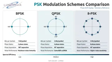
QPSK and 4-QAM produce mathematically identical modulated waveforms. Their four constellation points occupy the same locations in the I-Q plane — the difference is conceptual framing, not signal content.
How QPSK Modulation Works
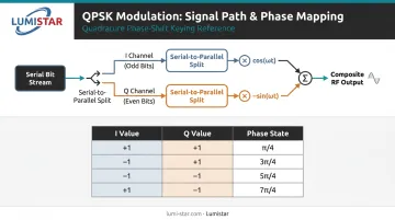
The QPSK modulator is a two-channel structure. The input binary data stream splits into I and Q streams, each independently modulates an orthogonal carrier, and the two modulated components sum into one composite RF signal.
Step 1: Serial-to-Parallel Conversion and NRZ Encoding
Incoming serial bits are demultiplexed into two parallel streams:
- Odd-indexed bits → in-phase (I) stream
- Even-indexed bits → quadrature (Q) stream
Each stream has symbol duration T_sym = 2T_b — twice the bit duration, so the symbol rate is half the bit rate.
Both streams then undergo NRZ polar encoding: binary 0 becomes −1, binary 1 becomes +1.
Unipolar encoding (0 and 1) must not be used. It nullifies one carrier component and corrupts the constellation entirely, a common mistake in simulation and hardware bring-up.
Step 2: I/Q Channel Modulation
The two encoded streams modulate orthogonal carriers:
- I channel: NRZ(I) × cos(2πf_c t)
- Q channel: NRZ(Q) × −sin(2πf_c t)
These carriers are 90° apart, so they occupy identical bandwidth without interfering with each other. The ±1 values of I and Q determine which of four phase states the composite signal takes. Each phase state maps uniquely to a 2-bit symbol:
| I | Q | Phase State |
|---|---|---|
| +1 | +1 | π/4 |
| −1 | +1 | 3π/4 |
| −1 | −1 | 5π/4 |
| +1 | −1 | 7π/4 |
Step 3: Signal Summing and Pulse Shaping
The I and Q modulated components are summed to produce the final QPSK signal. A root raised cosine (RRC) filter is applied to each channel before summing to control spectral occupancy and minimize inter-symbol interference (ISI).
Roll-off factor (α) examples from real standards:
- DVB-S2 (ETSI EN 302 307-1): α = 0.35, 0.25, or 0.20
- UMTS/3GPP: α = 0.22
How QPSK Demodulation Works
The coherent QPSK receiver correlates the received signal against both cosine and sine reference carriers, low-pass filters each product, and makes threshold decisions on each channel to reconstruct the original I and Q bits.
Step 1: Carrier Recovery
The receiver must generate a local oscillator phase- and frequency-synchronized with the transmitter's carrier. Any misalignment rotates the entire constellation, degrading symbol decisions.
Carrier recovery is the most operationally critical challenge in coherent demodulation. A Costas Loop tracks and corrects phase and frequency errors in QPSK receivers: it runs as two coupled feedback loops operating on the I and Q channels simultaneously.
Step 2: Coherent Detection on I and Q Channels
Demodulation proceeds as two independent BPSK demodulators running in parallel:
- Multiply received signal by cos(2πf_c t) → low-pass filter → I baseband component
- Multiply received signal by −sin(2πf_c t) → low-pass filter → Q baseband component
This parallel structure explains why QPSK achieves the same BER as BPSK per bit — each channel demodulates independently against its own orthogonal carrier.
A matched RRC filter (identical to the transmit-side filter) is applied at the receiver to maximize SNR at the sampling instant and eliminate ISI introduced by the transmit filter. The concatenation of transmit RRC and receive RRC produces a full raised cosine response with zero ISI at optimal sampling instants.
Step 3: Symbol Timing Recovery and Bit Decision
The receiver must identify the optimal sampling instant within each symbol period. Timing error detectors track and correct timing offset continuously. The Gardner TED, originally published for BPSK/QPSK sampled receivers, is widely used in both hardware and SDR implementations for this purpose.
Final decisions are straightforward:
- Filtered I sample positive → bit 1; negative → bit 0
- Filtered Q sample positive → bit 1; negative → bit 0
The I and Q bit sequences are then multiplexed back into the original serial stream. Where the transmitter used differential encoding, differential decoding is applied at this stage before output.
QPSK Waveforms and the Constellation Diagram
Time-Domain Appearance
At the transmitter output, the QPSK signal looks like a continuous sine wave whose phase shifts at symbol boundaries. In a timing diagram:
- The I-channel waveform is a BPSK-like signal at half the bit rate
- The Q-channel waveform is similarly BPSK-like, delayed relative to I
- The summed signal shows phase transitions at symbol boundaries
The problematic case: when both I and Q change state simultaneously, the composite signal undergoes an abrupt 180° phase jump. After band-limiting, this creates amplitude fluctuation — the core motivation for OQPSK and SOQPSK variants.
The Constellation Diagram
On the I-Q plane, the four QPSK symbols appear as points at (±√(Es/2), ±√(Es/2)) — four corners of a square, equidistant from the origin, separated by 90°.
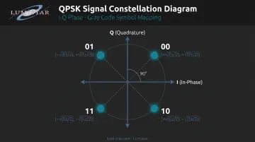
Gray coding assigns bit labels so adjacent constellation points differ by only one bit. This minimizes bit errors when noise causes a symbol decision to fall on a neighboring point rather than producing a two-bit error.
BER Proven Performance
That error-minimization benefit feeds directly into QPSK's bit error performance. According to Proakis and Salehi's Digital Communications, QPSK bit error probability is:
Pb = Q(√(2Eb/N0))
This matches BPSK exactly. The I and Q channels demodulate independently, so each bit sees the same noise margin as a BPSK bit.
The result looks different when engineers compare at equal symbol energy (Es) rather than equal bit energy (Eb). Since QPSK carries two bits per symbol, Es = 2Eb — so the Es/N0 comparison tells a different story than the Eb/N0 comparison. Same modulation, different frame of reference.
QPSK Variants and Their Role in Aerospace Telemetry
Standard QPSK's 180° phase jumps create real problems in RF systems. After band-limiting through a power amplifier, those transitions cause amplitude envelope fluctuations and spectral regrowth — interference into adjacent channels. Each variant below addresses this differently.
OQPSK
Offset QPSK delays the Q channel by half a symbol period (T_b) relative to I. Because I and Q can no longer change simultaneously, phase transitions are limited to ±90°. Amplitude fluctuations decrease substantially, and spectral containment after nonlinear amplification improves compared to standard QPSK.
π/4-QPSK
Symbols alternate between two QPSK constellations rotated 45° apart, limiting phase transitions to a maximum of 135°. The key advantage: compatibility with differential encoding, supporting both coherent and non-coherent demodulation. It's widely deployed in TDMA cellular systems, making it a practical choice where receiver complexity must be minimized.
SOQPSK-TG
SOQPSK-TG (Shaped Offset QPSK — Telemetry Group) is the most important variant for aeronautical telemetry. IRIG 106-22 Chapter 2 designates it as an ARTM Tier I bandwidth-efficient modulation. Key characteristics from IRIG 106-11 Appendix A:
- 99% power bandwidth of 0.78R (where R is bit rate)
- Necessary bandwidth of 1.3R
- BEP = 1×10⁻⁵ at 11.8–12.2 dB Eb/N0
- Continuous-phase pulse shaping eliminates abrupt transitions entirely
- Near-constant amplitude envelope, compatible with nonlinear amplifiers with minimal spectral regrowth
For airborne telemetry links, that 0.78R power bandwidth means SOQPSK-TG fits more efficiently into allocated spectrum than standard QPSK — which is why IRIG 106 programs default to it when adjacent-channel interference is a hard constraint.
DQPSK
Differential QPSK encodes data in phase transitions between successive symbols rather than absolute phase. This enables non-coherent demodulation and eliminates phase ambiguity at the receiver, though it carries a slightly higher BER penalty compared to coherent QPSK — a tradeoff that's acceptable when carrier recovery is impractical.
Lumistar's IRIG 106-Compliant Implementation
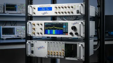
Lumistar's ground station and receiver products are built around these telemetry modulation requirements. All comply with IRIG 106 Chapter 4 Class I and Class II standards.
- LS-28-DRSM Series: Demodulates BPSK, QPSK, OQPSK, SQPSK, SOQPSK-TG, AQPSK, and AUQPSK at 1 kbps–50 Mbps (SOQPSK-TG: 5 kbps–50 Mbps); modulation formats are firmware-based personality modules, so DSP updates deploy as software rather than hardware swaps
- LS-35-R IF Receiver: Handles QPSK, OQPSK, SOQPSK, and AQPSK up to 40 Mbps
- LS-18 Series Transmitters: Support ARTM Tier 0/1/2 modulation — PCM/FM, SOQPSK-TG, and Multi-H CPM — for ground station verification and flight test simulation
Common Misconceptions About QPSK
A few persistent misconceptions trip up engineers working with QPSK — particularly in simulation environments. Here's where the logic breaks down.
"QPSK has worse BER than BPSK because its constellation points are closer together."
False. At equal Eb/N0, BER is identical. The confusion comes from comparing at equal symbol energy rather than equal bit energy. Since QPSK encodes two bits per symbol, the per-bit noise margin stays the same as BPSK.
Unipolar Encoding Doesn't Work for QPSK
QPSK requires NRZ polar encoding (−1/+1). Using unipolar (0/1) values collapses one carrier component to zero, destroying the constellation — and recovery is impossible. This appears regularly in simulation setups where default bit representations aren't verified before modulation.
QPSK Isn't Always the Right Choice
QPSK is an efficient middle ground, but not universally optimal. The better choice depends on your operating environment:
- Severe multipath or nonlinear amplifier conditions → OQPSK or SOQPSK-TG
- Spectral efficiency above 2 bits/symbol needed → evaluate 8-PSK or 16-QAM
- Very low SNR margins → BPSK provides greater noise immunity per symbol
Frequently Asked Questions
What is QPSK modulation and demodulation?
QPSK encodes two bits per carrier symbol using four distinct phase states. Demodulation recovers those bits by correlating the received signal against in-phase and quadrature reference carriers, then making threshold decisions on each channel to extract the original data.
How does QPSK modulation work?
The input bit stream splits into I and Q streams. Each stream is NRZ-encoded and multiplied by an orthogonal carrier — cosine for I, negative sine for Q. The two modulated signals sum to produce a carrier whose instantaneous phase reflects the 2-bit symbol value.
How do you demodulate a QPSK signal?
Coherent demodulation multiplies the received signal by local cosine and sine references, then low-pass filters each product. After symbol timing recovery, bit decisions come from the sign of each filtered I and Q sample, and the two streams are multiplexed back into serial output.
What is the difference between BPSK and QPSK?
BPSK encodes 1 bit/symbol using 2 phase states (180° apart); QPSK encodes 2 bits/symbol using 4 phase states (90° apart). Both achieve identical BER at equal Eb/N0, making QPSK the preferred choice when bandwidth is the constraining factor.
What is the difference between 4-QAM and QPSK?
They produce identical modulated RF waveforms — the four constellation points occupy the same I-Q plane locations. The distinction is conceptual: QPSK frames those points as phase shifts of a constant-amplitude carrier, while 4-QAM treats them as combinations of I and Q amplitude levels.
What is QPSK used for?
Key applications include satellite broadcast (DVB-S2), aeronautical flight test telemetry (IRIG 106/SOQPSK-TG), IEEE 802.11 wireless LAN, UMTS/3G cellular downlinks, and CDMA systems. It's the go-to choice when efficient RF bandwidth use and reliable performance in moderate-noise environments are both required.