Introduction
Precise time synchronization isn't optional in flight test telemetry — it's the foundation that makes multi-channel data correlation possible. For engineers working under IRIG 106 at aeronautical test ranges, a single misconfigured component in the timing chain can corrupt timestamps across every recording system downstream.
The IRIG-B demodulator sits right in the middle of that chain, and it's consistently the least-understood piece of the puzzle. Most telemetry documentation explains the IRIG-B format at length but glosses over what the demodulator actually does, how it's configured, and why it fails.
That gap has real consequences — a misconfigured input threshold or wrong modulation type selection can produce valid-looking output with subtly incorrect time codes, a fault that often surfaces only during post-flight data review. What follows covers the demodulator's role, configuration requirements, and the failure modes worth knowing before they cost you a test window.
Key Takeaways
- An IRIG-B demodulator strips the 1 kHz AM carrier from a modulated (B1xx) signal to recover the pulse-width-coded timing waveform — distinct from a decoder or generator
- Demodulation is only required for modulated signals; unmodulated DCLS (B0xx) signals feed directly into a decoder
- Input filtering, envelope detection, and threshold comparison produce a clean TTL, RS-232, or RS-422 output
- Key configuration parameters: input signal level, impedance, carrier frequency tolerance, output format, and IRIG-B variant (B120–B127)
- The most common failure causes are signal type mismatch (B1xx vs. B0xx) and impedance/level errors at the input terminal
What Is an IRIG-B Demodulator?
An IRIG-B demodulator is a hardware or firmware module that accepts an amplitude-modulated IRIG-B signal — where pulse-width-coded time data rides on a 1 kHz sine wave carrier — and performs AM demodulation to recover the baseband timing waveform.
Three components are often confused. The distinction matters:
| Component | Function |
|---|---|
| Demodulator | Strips the AM carrier to recover the pulse-width-coded waveform |
| Decoder | Interprets that waveform's bit timings to extract hours, minutes, seconds, day-of-year |
| Generator | Creates the IRIG-B time code signal from a reference clock source |
Both demodulation and decoding must happen in sequence to convert a modulated IRIG-B signal into usable time data. A system reporting "no time sync" may have a functioning demodulator front-end and a misconfigured decoder — they require separate diagnostic steps.
Where It Fits in the Timing Chain
The demodulator sits between the signal distribution network and the time code decoder:
GPS/Atomic Clock → IRIG-B Generator → Coaxial Distribution → Demodulator → Time Code Decoder → System Timestamp
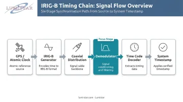
Skipping or misconfiguring the demodulator breaks the chain at that point. What passes downstream is a DC-level-shift (DCLS) pulse train — typically delivered as TTL, RS-232, or RS-422 — which the time code reader, RTU, or data acquisition computer then processes.
In Lumistar's ground station platforms — including the LS-28-DRSM series and LS-68-M multi-stream processor — IRIG-B demodulation runs as a firmware module inside the telemetry platform itself. No separate standalone demodulator unit is required, and the function is configured through software rather than external hardware adjustments.
How the IRIG-B Demodulation Process Works
The modulated IRIG-B input is a 1 kHz sine wave whose amplitude varies to encode the pulse-width-coded time data. Per IRIG Standard 200-16, Format B runs at 100 pulses per second with a 10 ms index count interval. The demodulator's job is to reconstruct that pulse train cleanly from the amplitude-modulated carrier.
Input Filtering and Signal Conditioning
The demodulator first applies a bandpass filter centered on 1 kHz to reject out-of-band noise and normalize the input signal. This step sets the sensitivity floor and overload ceiling for the entire demodulation process.
IRIG Standard 200-16 does not define a standard signal level for IRIG-B. Acceptable input voltage ranges vary significantly by device — the Microchip SyncServer S6x0 specifies 1 to 8 Vpp into 50Ω, while the Brandywine XMC SyncClock32 accepts 0.25 to 10 Vpp with an input impedance above 10kΩ. Always check the specific device datasheet before assuming the signal is within range.
Envelope Detection
Envelope detection extracts the modulating waveform from the carrier by following the peaks of the 1 kHz sinusoid. A rectifier-plus-low-pass-filter circuit produces a smoothed analog representation of the original pulse-width-coded signal.
The AM modulation ratio matters here. IRIG 200-16 Section 3.10 specifies a standard ratio of 10:3, with an allowable extracted range of 3:1 to 6:1. The carrier amplitude is at full level during the "high" portion of each bit and attenuated during the "low" portion — this amplitude difference is what the envelope detector tracks.
Threshold Comparison and Bit Decoding
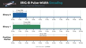
The recovered analog envelope passes through a comparator to produce a binary pulse train. IRIG 200-16 Section 3.6 defines the encoding rules that the comparator thresholds must discriminate:
- Binary 0: pulse "on" time = 0.2 × 10 ms interval = 2 ms
- Binary 1: pulse "on" time = 0.5 × 10 ms interval = 5 ms
- Position marker: pulse "on" time = 0.8 × 10 ms interval = 8 ms
Threshold misconfiguration is high-risk. An error here can push the decoded time off by up to a full bit period — a 10 ms slip. That margin is unacceptable in systems governed by IRIG 106 Chapter 10, which targets 100 ns resolution through its 10 MHz relative time counter.
Getting the comparator thresholds right is therefore a prerequisite before validating any downstream timing output from the demodulator.
Key Configuration Parameters
Input Signal Level and Impedance
Match the demodulator input to the source impedance:
- 50Ω — standard for coaxial distribution (RG58)
- 75Ω — RG59 coaxial cable
- 600Ω — balanced twisted-pair distribution
- High-Z (>10kΩ) — passive monitoring/bridging applications
Lumistar's LS-18-P1 portable telemetry system, for example, offers software-selectable input termination of 100Ω or >10kΩ, providing flexibility for different installation configurations. Under-level signals cause lock failure; over-level signals clip the waveform and corrupt the envelope. Measure signal amplitude at the demodulator input terminal before adjusting any sensitivity settings.
Carrier Frequency Lock and Tolerance
The nominal carrier is 1 kHz, but real-world sources drift. Configure the acceptance bandwidth to accommodate expected drift without locking onto interference. Monitor lock-status indicators — LED, serial status bit, or software flag — during commissioning to confirm the demodulator has acquired the carrier before trusting any decoded time output.
Output Format Selection
Choose the output format based on what the downstream receiver accepts:
- DCLS/TTL — short coaxial runs to nearby equipment
- RS-232 — direct connection to a data acquisition computer or RTU
- RS-422 differential — longer cable runs where noise immunity is needed
The output format must match the downstream receiver's input specification. A mismatch here won't cause a lock failure — the demodulator will report normal operation while the decoder receives an unusable signal.
IRIG-B Format Variant Selection
All B1xx variants use a 1 kHz carrier, but their coded expressions differ. The demodulator hardware handles carrier removal regardless of variant; the downstream decoder must be configured to match what's actually being transmitted:
| Variant | Coded Expressions |
|---|---|
| B120 | BCDTOY + CF + SBS |
| B121 | BCDTOY + CF |
| B122 | BCDTOY only |
| B123 | BCDTOY + SBS |
| B124 | BCDTOY + BCDYEAR + CF + SBS |
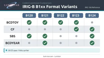
Note: B123 is a 1 kHz carrier variant — not 10 kHz. A decoder configured for B122 receiving a B120 signal will miss the control functions and straight binary seconds fields, producing incomplete time data even when the demodulator itself is locking correctly.
Timing Accuracy and Delay Compensation
AM IRIG-B introduces propagation and detection delay relative to the original on-time marker. Microchip/Tekron documentation cites AM IRIG-B accuracy at under 2 microseconds at the port, compared to under 100 ns for DCLS — a difference that directly affects multi-channel synchronization budgets. Cable propagation adds approximately 5.25 ns/m for typical STP cable, which accumulates in large ground station installations.
Lumistar's LS-50-E PCIe decommutator specifies an IRIG reader latency of 2 microseconds maximum, consistent with this figure. For flight test programs under IRIG 106 where sub-microsecond correlation is required, include AM demodulator latency and cable delay in the timing budget from the start.
Common Issues and Misconceptions
Confusing B1xx and B0xx Signal Types
This is the most frequent configuration error. Connecting an unmodulated DCLS signal (B0xx) to a demodulator input causes the demodulator to treat square wave transitions as amplitude variations — the output is garbled, and the system may still report "lock" depending on the hardware.
Before wiring, check the signal on an oscilloscope:
- DCLS (B0xx): clean square wave, fixed amplitude, no sinusoidal carrier
- AM (B1xx): sinusoidal 1 kHz carrier with visible amplitude modulation at the bit transitions
No demodulator is needed for DCLS. That signal feeds directly into the decoder.
Signal Level and Impedance Mismatch
IRIG 200-16 does not define a universal signal level, so cable attenuation, splitter losses, and termination errors can pull the signal below the demodulator's sensitivity floor without any obvious indication.
Symptoms: intermittent lock loss, jittery decoded time, or time jumps under vibration.
Diagnostic approach: measure signal amplitude at the demodulator input terminal with an oscilloscope — not at the source — before adjusting any gain or sensitivity settings.
Treating Demodulation and Decoding as One Step
These are distinct functions. A system with no time sync may have:
- A correctly demodulating front-end with a misconfigured decoder (wrong variant, wrong bit-width thresholds)
- A correctly configured decoder receiving a garbled waveform due to over-level drive or impedance mismatch at the demodulator input
Diagnose each stage independently. Check the demodulated pulse train on the output connector before assuming the demodulator has failed.
Frequently Asked Questions
What is the difference between a modulated and unmodulated IRIG-B signal?
Modulated IRIG-B (B1xx) encodes the pulse train on a 1 kHz AM sine wave carrier, making it suitable for long-distance coaxial distribution. Unmodulated IRIG-B (B0xx) uses direct DC-level shifts without a carrier, offering timing accuracy better than 100 ns but over shorter cable runs only.
What does an IRIG-B demodulator output?
The output is a reconstructed DC-level-shift pulse train representing the original IRIG-B timing waveform, delivered as TTL, RS-232, or RS-422 depending on configuration. This output is ready for a time code decoder or data acquisition system to interpret.
Do I need a demodulator for unmodulated DCLS IRIG-B signals?
No. DCLS signals have no carrier to remove and feed directly into a time code decoder. Routing a DCLS signal through a demodulator will produce incorrect output — the demodulator will misinterpret the square wave transitions as amplitude modulation.
What is the difference between an IRIG-B demodulator and an IRIG-B decoder?
A demodulator removes the AM carrier to recover the pulse-width-coded waveform. A decoder then interprets that waveform's bit timings to extract hours, minutes, seconds, and day-of-year values. Both steps must occur in sequence when processing a modulated IRIG-B signal.
What input signal level does an IRIG-B demodulator typically require?
IRIG 200-16 does not define a standard signal level. Requirements vary by device — typical ranges span 0.25 to 10 Vpp depending on the unit. Always verify signal amplitude at the input terminal and consult the specific device datasheet before configuration.
Which IRIG-B format variants does a demodulator need to support?
The demodulator hardware handles the 1 kHz carrier common to all B1xx variants. The downstream decoder must be configured to match the specific variant received (B120, B122, B123, and so on) to correctly parse control functions, SBS, and year fields within the frame.