Introduction
A single PCM telemetry downlink now has to carry HD video, MIL-STD-1553 and ARINC 429 bus data, raw Ethernet frames, and traditional analog measurements — all simultaneously, all in real time.
The problem: PCM frames are rigid, fixed-length structures. Packet data is variable-length and asynchronous. Getting one to carry the other requires a well-defined standard.
That standard is IRIG 106 Chapter 7, titled "Packet Telemetry Downlink." It defines exactly how variable-length data packets can be asynchronously inserted into a Chapter 4 PCM stream, enabling a single downlink to simultaneously carry legacy and modern data types.
First published in 2015 as part of IRIG 106-15, with subsequent revisions in 2017 and 2019, Chapter 7 adoption across hardware and software vendors remains uneven. Not every vendor supports the same revision — a gap engineers need to verify before specifying a system.
This guide covers:
- What Chapter 7 defines and why it exists
- How the PCM frame structure accommodates packet data
- Packet multiplexing mechanics
- Error protection schemes
- What to verify when selecting compliant equipment
Key Takeaways
- Chapter 7 encapsulates variable-length packets (Ethernet, Chapter 10/11, TmNS) inside fixed-frame Chapter 4 PCM streams
- Each minor frame opens with a 32-bit sync pattern and a Minor Frame Header carrying byte offsets and flags
- Packets can span multiple minor frames; Low-Latency Packets let high-priority data bypass the queue
- Golay (24,12,8) code protects header fields; optional Reed-Solomon covers the full PCM stream
- Confirm whether each component in your telemetry chain supports the 2015, 2017, or 2019 revision before procurement
What Is IRIG 106 and Where Does Chapter 7 Fit?
IRIG 106 is the governing telemetry standard maintained by the Range Commanders Council (RCC) Telemetry Group. Per the official IRIG 106 site, it ensures interoperability across RCC member ranges — spanning airborne data acquisition through ground-based reception and processing. It's a US government standard applied across defense, aerospace, and federal test range programs.
How the Standard Is Organized
Each chapter addresses a distinct layer of the telemetry chain:
| Chapter | Title | Function |
|---|---|---|
| Chapter 4 | PCM Standards | Defines the serial PCM bit stream format and frame structure |
| Chapter 7 | Packet Telemetry Downlink | Defines packet encapsulation within a Chapter 4 PCM stream |
| Chapter 10 | Digital Recording Standard | Defines data acquisition and recording formats |
| Chapter 11 | Recorder Data Packet Format | Defines packet formats for multiplexed digital inputs |
| Chapter 24 | Message Formats | Defines iNET TmNS message structures |
Chapter 7 acts as a transport layer — it doesn't define the data formats themselves, but specifies how those formats ride inside a PCM downlink.
The Gap Chapter 7 Fills
Before Chapter 7, PCM streams carried only fixed, synchronous data. There was no standard method for inserting variable-length, asynchronously generated data — like Ethernet frames or Chapter 10/11 packets — into a real-time downlink. Chapter 7, introduced in IRIG 106-15, addressed this by standardizing how asynchronous packets are inserted into the PCM stream.
Subsequent revisions expanded that foundation:
- IRIG 106-17 (Task TG-144): Added support for defining a PCM minor frame subset for Chapter 7 data
- IRIG 106-19 (Task TG-158): Improved troubleshooting support and reduced acronym ambiguity
What IRIG 106 Chapter 7 Defines: Packet Telemetry in a PCM Stream
Packets, Headers, and Payloads
A packet is a data payload wrapped with control information — a header that identifies the data type, length, and sequence. The header carries addressing and routing metadata; the payload carries the actual content. Chapter 7 formalizes this structure for telemetry applications.
The core technical challenge is that PCM minor frames are fixed in length, while packets are not. A single Ethernet frame may be longer than one minor frame. A small status packet may be much shorter. Chapter 7 defines how to handle both cases correctly.
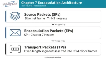
In current IRIG 106-23 terminology, the architecture uses three layers:
- Source Packets (SPs) — the original data (Ethernet frame, TmNS message, etc.)
- Encapsulation Packets (EPs) — the SP wrapped with a Chapter 7 header
- Transport Packets (TPs) — fixed-length segments of the EP stream, inserted into PCM minor frames
Supported Data Types
Current IRIG 106-23 Chapter 7 defines these Source Packet content types:
| Content Value | Type |
|---|---|
| 4'b0000 | Fill SP |
| 4'b0001 | Application-Specific SP |
| 4'b0010 | Test Counter SP |
| 4'b0011 | Chapter 11 SP |
| 4'b0100 | Raw Ethernet MAC Frame SP |
| 4'b0101 | Internet Protocol (IP) SP |
| 4'b0110 | Chapter 24 TmNS Message SP |
Note on edition differences: The original IRIG 106-15 Chapter 7 used Chapter 10 packet terminology. Current IRIG 106-23 uses Chapter 11 SP language. If your system references Chapter 10 packets specifically, confirm which edition your equipment implements.
Fill Packets Keep the Stream Continuous
Chapter 7 does not allow gaps. When no payload data is available, fill packets are inserted automatically — each fill byte has the value 0xAA. This guarantees the ground receiver always processes a valid, complete frame — eliminating the need for gap-handling logic on the receive side.
PCM Frame Structure: Minor Frames, Sync Patterns, and the Minor Frame Header
Frame Synchronization Patterns
Each minor frame begins with a 32-bit Frame Synchronization Pattern that allows the ground receiver to locate frame boundaries in the continuous PCM bit stream.
Per IRIG 106-15 Chapter 7:
- Without Reed-Solomon error correction:
0xFE6B2840 - With optional Reed-Solomon error correction:
0x1ACFFC1D
The sync pattern is non-negotiable — without it, the receiver has no reliable way to identify where each frame starts.
Frame Data Payload
Following the sync pattern, the data payload area uses 8-bit (1-byte) words. Per IRIG 106-15, the total data bytes available per minor frame is N × 223 bytes, where N is an integer from 1 to 8. This sizing aligns with the optional Reed-Solomon outer code.
All frames must be the same fixed length — this consistency is what makes PCM decommutation manageable.
The Minor Frame Header
The Minor Frame Header (MFH) immediately follows the sync pattern. It has two parts:
Unprotected 8-bit first half:
- Bits 7–4: Stream ID (identifies up to 16 different data streams)
- Bits 3–2: Reserved
- Bits 1–0: Version (identifies which Chapter 7 revision is in use)
Golay-protected 12-bit second half:
- Bits 10–0: Offset to First Packet Header — the byte position of the first new packet header within this frame
- Bit 11: LLP Exists flag — indicates whether one or more Low-Latency Packets are present
The offset field is the key to correct packet reconstruction. Because a packet can start anywhere within a frame, the decoder cannot simply scan from byte zero — the MFH offset tells it exactly where to look.
Miss this field, and the decoder loses its place in the packet stream with no clean recovery path.
Asynchronous Packet Multiplexing and Low-Latency Packets
How Multiplexing Works
Asynchronous Packet Multiplexing (APM) means packets are not synchronized to the PCM frame clock. A single large packet may span multiple minor frames; several small packets may share one frame.
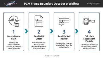
The decoder's workflow at each frame boundary:
- Locate the frame start using the sync pattern
- Read the MFH to find the offset to the first packet header
- Read that packet header to get the packet's length and type
- Calculate where subsequent packets begin from their own length fields
The Encapsulation Packet (EP) header is transmitted as two 24-bit Golay-protected words, encoding 12 bits each. Key fields include:
- Length (bits 15–0): Data length in bytes, excluding the header
- Fragment (bits 17–16):
2'b00Complete,2'b01First Fragment,2'b10Middle Fragment,2'b11Last Fragment - Content (bits 21–18): Data type identifier (see table above)
- CRC flag (bit 23): Present in current 106-23 EP headers
Packet Fragmentation for Large Payloads
When a Source Packet is ≥ 64 KB (0x10000 bytes), fragmentation is required. Three rules govern this process:
- Fragments are transmitted sequentially — they are never interleaved with other fragmented streams
- Only Low-Latency Encapsulation Packets (LLEPs) may be inserted between fragments in a sequence
- The Fragment field in the EP header identifies each fragment's position in the sequence
Low-Latency Packets
Control messages and safety-critical measurements cannot wait in the normal packet queue. Low-Latency Packets (LLPs) — called Low-Latency Encapsulation Packets (LLEPs) in current 106-23 — bypass that queue entirely.
LLEPs have two hard constraints:
- They must fit entirely within a single minor frame (no spanning)
- Each LLEP must be immediately followed by an end byte: 0xFF if another LLEP follows, 0x00 if it is the last one in the frame
The LLP Exists flag in the MFH tells the decoder to process LLEPs before handling standard packets in that frame.
Packet Types, Error Protection, and Implementation Considerations
Error Protection: Golay and Reed-Solomon
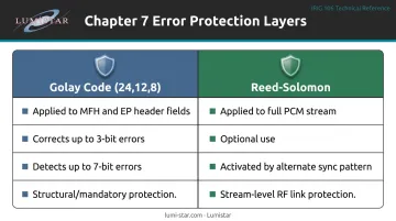
Chapter 7 uses two error protection mechanisms that operate at different layers.
Golay Code (structural protection):
The extended binary Golay code has parameters (24,12,8) — it encodes 12 data bits into a 24-bit codeword. Applied to all MFH and EP header fields, it:
- Corrects up to 3-bit errors
- Detects up to 7-bit errors
A single corrupted bit in a structural field — the MFH offset, the packet length, the fragment indicator — can cause the decoder to lose frame lock and drop multiple subsequent packets. Golay protection guards against this.
Reed-Solomon (stream-level protection, optional):
Per IRIG 106-15, an optional Reed-Solomon outer code can be applied to the entire PCM stream for additional protection over noisy RF links. The alternate sync pattern (0x1ACFFC1D) and N × 223 frame sizing signal its use.
IRIG 106-15 original text confirms this mechanism; however, explicit RS parameters were not verified in current 106-23 extraction. Confirm with your equipment vendor whether this capability applies to your specific implementation.
Implementation Considerations
Engineers specifying or deploying Chapter 7 systems should work through this checklist:
- Confirm that every component — airborne encoder, ground bit synchronizer, PCM decommutator, data processor — supports the same Chapter 7 revision. Interoperability across the chain depends on it.
- Verify that bit synchronizers and PCM decommutators can parse the MFH offset field and reconstruct variable-length packets spanning multiple minor frames.
- If your system was designed to the 2015 standard, check how your software handles the Chapter 11 SP content values used in current 106-23 versus the Chapter 10 packet terminology from earlier revisions.
- PCM-to-Ethernet bridging — stripping Chapter 7 formatting to forward recovered packet data over Ethernet — is a vendor-implemented capability, not a feature defined within the RCC standard itself. Confirm support explicitly with your vendor.
Lumistar manufactures IRIG 106-compliant telemetry hardware across the full ground station chain, including bit synchronizers, PCM decommutators, and integrated ground station systems. For specific questions about Chapter 7 compatibility, contact their engineering team at 760-431-2181 or sales@lumistar.net.
Frequently Asked Questions
What is IRIG 106 Chapter 7?
IRIG 106 Chapter 7, titled "Packet Telemetry Downlink," defines how variable-length data packets (Chapter 11 data, Ethernet frames, Chapter 24 TmNS messages) are asynchronously inserted into a Chapter 4 PCM telemetry stream for real-time downlink during flight test. First introduced in IRIG 106-15, it replaced earlier Chapter 10 packet terminology in subsequent editions.
What is the IRIG standard?
IRIG 106 is the Range Commanders Council's governing standard for telemetry in test and evaluation programs, covering airborne data acquisition through ground-based reception and processing. It is a US government standard used across defense, aerospace, and federal test range programs including Air Force, Navy, Army, and NASA facilities.
What is the difference between IRIG 106 Chapter 7 and Chapter 10?
Chapter 10 defines the data packet and recording format for telemetry data types: what the data contains and how it is structured. Chapter 7 defines how those packets are encapsulated and transported inside a PCM stream for real-time downlink.
What packet types are supported by IRIG 106 Chapter 7?
Current IRIG 106-23 Chapter 7 supports Fill SPs, Application-Specific SPs, Test Counter SPs, Chapter 11 SPs, Raw Ethernet MAC Frame SPs, Internet Protocol (IP) SPs, and Chapter 24 TmNSMessage SPs. The original 2015 edition used Chapter 10 packet terminology rather than Chapter 11.
What is asynchronous packet multiplexing in IRIG 106 Chapter 7?
Asynchronous packet multiplexing is the method by which variable-length packets are inserted into fixed-length PCM minor frames without synchronization to the frame clock. Packets can span multiple frames or share a single frame. The Minor Frame Header offset field directs the decoder to the correct packet boundaries in either case.
How does Golay code protect data in IRIG 106 Chapter 7?
The extended binary Golay code (24,12,8) encodes 12 bits of structural data into 24-bit protected words, applied to all MFH and EP header fields. It corrects up to 3-bit errors and detects up to 7-bit errors. This prevents a single transmission error from corrupting frame structure and causing loss of multiple downstream packets.