Every performance validation run, every safety monitoring mission, every compliance demonstration at a federal test range depends on a PCM chain that works correctly. Get it wrong and you don't just lose data; you lose the test.
This guide covers the full PCM telemetry architecture — from analog signal conditioning on the aircraft to decommutated engineering data on the ground — along with the IRIG 106 standards that govern it all.
Key Takeaways
- PCM converts analog sensor signals into a serial binary data stream transmitted wirelessly from aircraft to ground
- Multiple sensor channels are combined into structured frames using time-division multiplexing, governed by IRIG 106 Chapter 4
- Ground stations receive, synchronize, and decommutate the stream to recover individual measurement channels
- The Range Commanders Council maintains PCM as an active standard in IRIG 106-24R1, alongside network telemetry chapters
- Ethernet-based alternatives (iNET/TmNS) are gaining ground, yet PCM stays essential for deterministic, low-overhead telemetry applications
What Is PCM Telemetry?
The Encoding Fundamentals
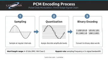
Pulse-code modulation (PCM) converts analog sensor signals into digital form through three steps: sampling the signal at regular intervals, quantizing each sample to a discrete amplitude level, and encoding the result as binary data — as defined by Federal Standard 1037C. Two parameters control the quality of that conversion:
- Word length (bit depth) — determines amplitude resolution; IRIG 106 Class I supports 4 to 32 bits per word
- Sample rate — determines time-domain resolution; per the Nyquist requirement, the sampling frequency must be at least twice the highest frequency component of the signal being sampled
Get either parameter wrong and you introduce quantization error or aliasing into your data before transmission even begins.
From Audio to Aerospace
PCM is also the encoding method behind digital audio, but aeronautical flight test PCM telemetry is a different discipline entirely. IRIG 106 — developed and maintained by the Telemetry Group of the Range Commanders Council — defines PCM telemetry specifically for interoperability in aeronautical applications at RCC member ranges.
In practice, that means transmitting dozens or hundreds of sensor channels simultaneously over a single RF link, with the ground station recovering each measurement in real time.
PCM vs. iNET/TmNS
The key architectural difference comes down to structure:
| Attribute | PCM Telemetry | iNET/TmNS |
|---|---|---|
| Data structure | Fixed-length frames, TDM | Ethernet-based packets |
| Timing | Deterministic | Variable latency |
| Standard | IRIG 106 Chapter 4 | IRIG 106 Chapters 21–28 |
| Ground infrastructure maturity | Decades of deployment | Growing adoption |
IRIG 106-24R1 covers both standards. The choice between them depends on test range requirements, infrastructure, and specific program objectives.
How a PCM Telemetry System Works
A PCM telemetry system moves data through three distinct phases: onboard acquisition and encoding, RF transmission, and ground-side recovery.
Step 1: Signal Conditioning, Sampling, and Encoding
On the aircraft, each sensor's analog output goes through signal conditioning — typically a low-pass filter to remove high-frequency noise — before reaching the analog-to-digital converter (ADC). The ADC samples the signal and converts it to a binary word.
Word length in IRIG 106 Class I ranges from 4 to 32 bits. Different sensors get different sample rates based on their dynamics:
- Slow-changing parameters (fuel level, air temperature) — low sample rates
- Fast-changing parameters (acceleration, vibration) — high sample rates
- Nyquist compliance required for all channels
Step 2: Commutation, Framing, and RF Transmission
The encoder's multiplexer assembles binary words from each channel sequentially into a minor frame using time-division multiplexing (TDM). Each minor frame begins with a Frame Sync pattern, a unique 16–33 bit binary sequence chosen for its low probability of occurring naturally in the data.
Minor frames aggregate into a major frame, which contains at least one sample of every parameter. Once the major frame is assembled, the PCM stream is frequency-modulated onto a carrier — a technique known as PCM/FM, or filtered continuous phase frequency shift keying (CPFSK) per IRIG/RCC — and transmitted via an onboard antenna in the L, S, or C band.
Key transmission parameters set at this stage:
- Modulation: PCM/FM (CPFSK) per IRIG 106
- Carrier bands: L, S, or C band depending on range and link budget
- Bit rate: determined by total channel count and sample rate requirements
Step 3: Ground Reception, Bit Sync, Frame Sync, and Decommutation
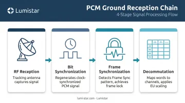
The ground station receive chain has four sequential functions:
- RF reception — tracking antenna captures the signal; RF receiver recovers the raw PCM stream
- Bit synchronization — locks onto data transitions and regenerates a clean, clock-synchronized PCM signal
- Frame synchronization — searches for the known Frame Sync pattern, verifies recurrence at the expected interval, and achieves frame lock
- Decommutation — maps each word in the frame to its channel, applies engineering unit scaling, and delivers usable measurement data for display and archiving
The decommutator relies on a TMATS (Telemetry Attributes Transfer Standard, IRIG 106 Chapter 9) configuration file to know where each parameter lives in the frame. If that file doesn't match the encoder's actual format, the ground system will lock onto the frame and decode every word — but the engineering unit values will be wrong, often with no obvious error indication.
PCM Frame Structure: Minor Frames, Major Frames, and Commutation
Minor Frames and Major Frames
The minor frame is the fundamental structural unit: a fixed-length sequence of binary data running from one Frame Sync pattern to the next. Per IRIG 106 Chapter 4 Class I:
- Maximum minor frame size: 8,192 bits or 1,024 words
- Maximum minor frames per major frame: 256
The major frame is the collection of minor frames needed to include at least one sample of every parameter in the format. The Sub-Frame ID (SFID) counter tracks position within the major frame, allowing the decommutator to correctly identify subcommutated channels.
Subcommutation and Supercommutation
These two mechanisms handle the fact that not all sensors need the same sample rate:
- Subcommutation — assigns a slow-changing parameter to a word position that rotates across multiple minor frames, sampling it at a fraction of the frame rate (for example, cabin temperature or fuel quantity)
- Supercommutation — assigns a fast-changing parameter to multiple word positions within a single minor frame, achieving a higher effective sample rate (for example, vibration or structural acceleration)
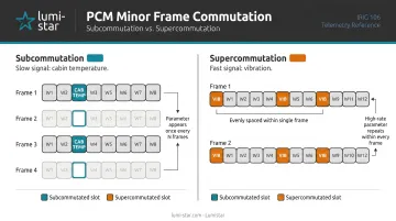
IRIG 106 requires that supercommutated samples be evenly spaced within the minor frame for Class I formats.
Line Coding Conventions
Once the frame structure is defined, the PCM stream must be encoded for transmission. IRIG 106 permits six line coding conventions, with only one used within a single stream:
- NRZ-L, NRZ-M, NRZ-S
- Bi-Phase-L, Bi-Phase-M, Bi-Phase-S
NRZ-L is the most commonly used in practice. When long runs of identical bits are expected, Randomized NRZ-L (RNRZ-L) ensures sufficient bit transitions for clock recovery. IRIG 106 requires the 15-bit regeneration pattern when RNRZ-L is transmitted and recommends avoiding transition gaps longer than 64 bit intervals.
Key Factors That Affect PCM Telemetry Performance
Bit Rate and Timing Accuracy
Bit rate selection must accommodate total channel throughput while staying within RF bandwidth allocation. IRIG 106 Chapter 4 sets hard limits:
- Bit rate must remain within 0.1% of the specified nominal value
- Bit jitter must not exceed ±0.1 of a bit interval
- Bit rates greater than 10 Mbps are a Class II characteristic
Violate either tolerance and you introduce systematic errors that can destabilize frame lock.
Signal Quality and Bit Error Rate
The quality of the received signal directly determines the Bit Error Probability (BEP). Per IRIG 106 Appendix C, a well-designed PCM/FM system with NRZ-L coding achieves BEP 10⁻⁶ at approximately 13 dB receiver IF SNR under standard conditions.
Key factors affecting received signal quality:
- Transmitter power and antenna gain
- Propagation distance and geometry
- Multipath interference from terrain or airframe reflections
- Atmospheric conditions
High BEP can cause the frame synchronizer to lose lock, producing data gaps. Ground receivers use error tolerance settings in the frame synchronizer to maintain lock through brief signal degradations.
SWaP Constraints — Airborne and Ground
Airborne encoders must fit within strict size, weight, and power budgets on the test aircraft. The same pressure has driven major improvements on the ground side.
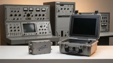
Lumistar's LS-28-DRSM and LS-68-M series illustrate how far SWaP optimization has come. Less than 20 years ago, a typical flight test telemetry ground station stood 8 feet tall, weighed 250 kg, and consumed thousands of watts.
The LS-28-DRSM brick form factor measures 6.00 × 4.00 × 1.60 inches and weighs under 1 kg. At roughly 40 watts, it delivers dual-channel RF reception, diversity combining, bit synchronization, frame synchronization, and data recording. The portable LS-28-DRSM-P1 "lunchbox" configuration weighs around 15 pounds and is compact enough to carry on a commercial flight.
TMATS Configuration Integrity
TMATS accuracy is a hard requirement. If the TMATS file used for decommutation does not precisely match the encoder's format, the recovered data will be wrong — and may look valid on screen while being completely meaningless.
Maintaining data integrity requires:
- Word positions, word lengths, and sample rates that exactly match the encoder configuration
- Engineering unit scaling verified before and after any format change
- Version-controlled TMATS files shared consistently between the flight test data system and the ground decommutator
Format changes mid-flight (a Class II capability) require careful format-change identification (FFI) mechanisms to prevent silent data corruption.
Common Misconceptions About PCM Telemetry
"PCM Is Being Replaced Everywhere"
IRIG 106-24R1 still includes Chapter 4 (PCM Standards) alongside Chapters 21–28 (network telemetry/TmNS), and both are actively maintained by the Range Commanders Council. Programs with existing PCM range infrastructure, deterministic data requirements, and mature ground systems have no obligation to migrate — and often good reasons not to.
"Frame Lock Means the Data Is Good"
Frame synchronization confirms only the structural integrity of the bit stream, not data accuracy. Each of the following can produce frames that pass sync checks while delivering meaningless or wrong-scaled values:
- A mismatched TMATS file that misidentifies parameter locations
- An incorrectly configured encoder applying the wrong bit rate or word length
- A failed sensor outputting a constant or out-of-range signal
End-to-end data integrity requires calibration verification and cross-checks. Frame lock status is a starting point, not a guarantee.
When PCM May Actually Not Be the Right Choice
PCM's fixed-frame, time-division-multiplexed architecture has real constraints. Consider alternatives when:
- The parameter set is large, dynamic, and frequently changing between missions
- Bandwidth demands push into Class II complexity that a single PCM stream can't efficiently handle
- The ground infrastructure is already fully Ethernet-native and a PCM chain would add unnecessary conversion overhead
Range requirements, existing infrastructure, and test objectives should drive the architecture decision. Neither PCM nor network-based telemetry is the right answer in every program.
Frequently Asked Questions
What does PCM stand for in data communication?
PCM stands for Pulse Code Modulation, a method of representing analog signals as a series of discrete binary values at uniform time intervals. It enables reliable digital transmission of sensor data over communications links, including RF telemetry systems used in flight test.
What is IRIG 106 Chapter 4 and why does it matter for PCM telemetry?
IRIG 106 Chapter 4 is the standard published by the Inter Range Instrumentation Group that defines the structure, bit rates, frame formats, and line coding rules for PCM telemetry. Compliance ensures that airborne encoders and ground stations from different manufacturers can interoperate across programs and test ranges.
What is the difference between a minor frame and a major frame in PCM telemetry?
A minor frame is the basic repeating unit of a PCM stream, bounded by Frame Sync patterns and containing one sample of each full-rate channel. A major frame is the collection of minor frames needed to include at least one sample of every parameter — including those sampled at submultiple rates via subcommutation.
What is decommutation in PCM telemetry?
Decommutation is the ground-side process of extracting individual measurement channels from the PCM bit stream using the known frame format (typically described in a TMATS file) and converting raw binary words into calibrated engineering units for display, analysis, and archiving.
What is the difference between subcommutation and supercommutation?
Subcommutation assigns a slow-changing parameter to a word position that rotates across multiple minor frames, reducing its sample rate below the frame rate. Supercommutation does the opposite — placing a fast-changing parameter in multiple word slots within a single minor frame to capture it more than once per frame.
When should a program consider switching from PCM to iNET telemetry?
iNET is worth evaluating when the parameter set is large and frequently changing, bandwidth demands outpace a single PCM stream, or the ground infrastructure is already Ethernet-native. Programs with deterministic data requirements often retain PCM or adopt a hybrid approach. Lumistar's LS-28-DRSM and LS-68-M series support both PCM and TMoIP Ethernet output from the same hardware platform.