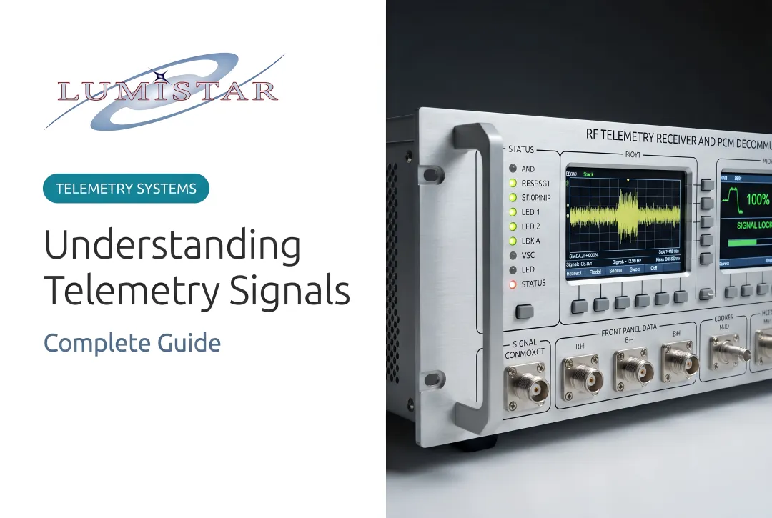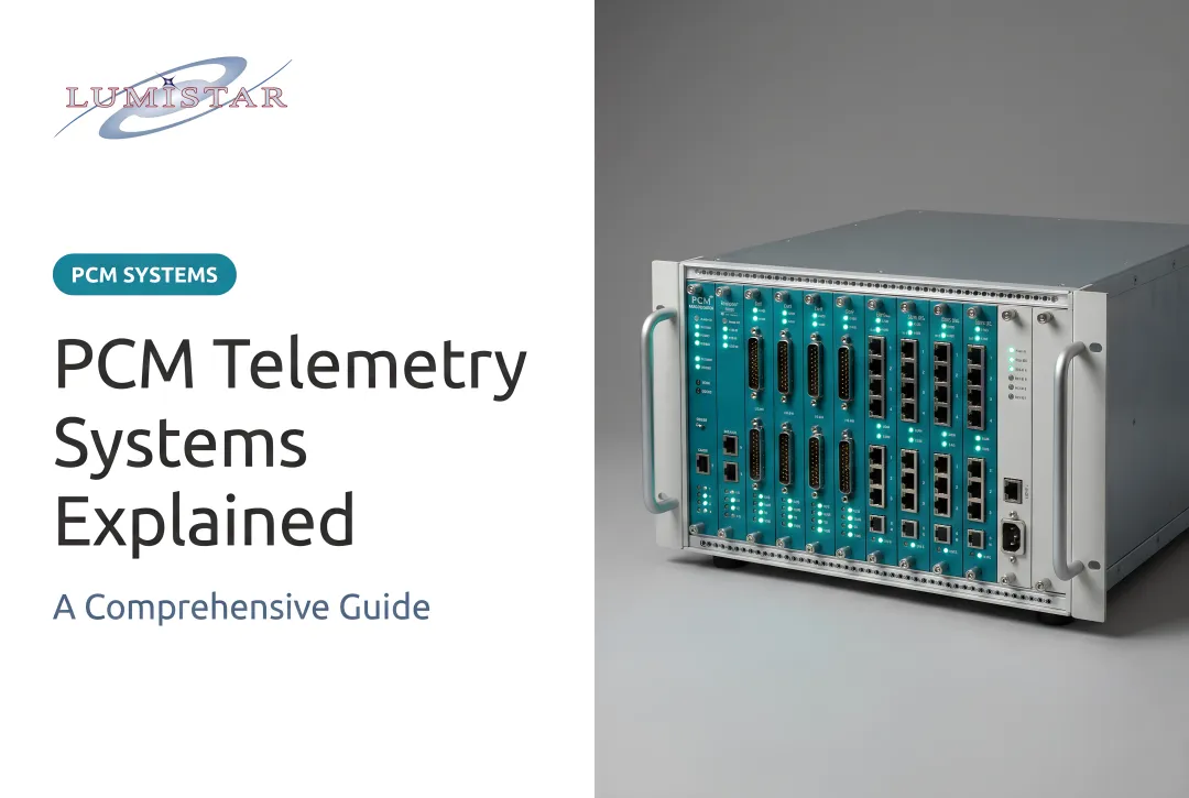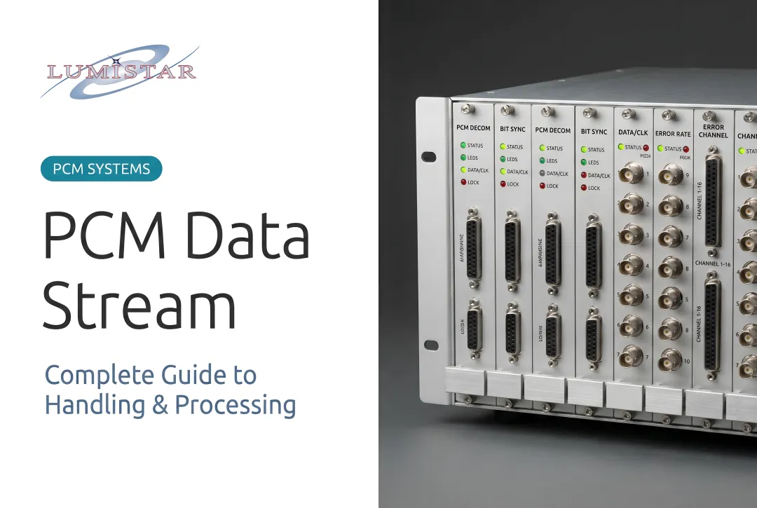
The problem is that stopping there leaves measurable performance on the table. Research from Sandia National Laboratories shows that optimally detecting PCM/FM yields roughly 3.5 dB improvement at BER = 10⁻⁵ over the traditional limiter-discriminator approach — a significant margin in any range-limited or interference-prone flight test environment.
This article is for telemetry engineers, flight test instrumentation specialists, and systems integrators working within IRIG 106-compliant programs who need to understand PCM/FM at the modulation-theoretic level: what it actually is, why the phase modulation reinterpretation matters, and what it means for receiver selection.
Key Takeaways
- PCM/FM (ARTM Tier-0) is a Continuous Phase FSK scheme with modulation index h = 0.7, approximable as h = 2/3
- That h = 2/3 approximation reinterprets PCM/FM as ternary PSK, enabling coherent detection with ~3.5 dB BER improvement over limiter-discriminator at BER = 10⁻⁵
- Approximating h = 2/3 does not alter the transmitted spectrum — the signal still fits the IRIG spectral mask
- Optimally decoded PCM/FM outperforms ARTM Tier-1 and Tier-2 in error rate, but at lower spectral efficiency
- Receiver architecture — not just hardware capability — is the critical engineering decision
What Is PCM/FM as a Phase Modulation Scheme?
The CPM Foundation
PCM/FM transmits digital data by filtering an NRZ-encoded PCM bitstream and using it to frequency-modulate an RF carrier. The result is a constant-envelope signal — and because phase is the integral of frequency, every bit transition produces a continuous phase change rather than an abrupt jump. That property places PCM/FM squarely in the Continuous Phase Modulation (CPM) family.
IRIG 106-22 Chapter 2 formalizes this: it classifies unfiltered PCM/FM as full-response CPM and filtered PCM/FM as partial-response CPM with frequency pulses spanning L = 3 symbol times. The standard also sets the modulation index at h = 0.7, corresponding to a peak deviation of 0.35 × bit rate.
The Modulation Index and Why h = 0.7
The modulation index h defines how far the carrier phase advances or retards per bit period:
- h = 0.7: Each bit contributes ±0.7π radians of phase shift
- Theoretical CPFSK optimum: h = 0.715, yielding maximum minimum squared Euclidean distance (d²min = 2.434)
- Why h = 0.7: Chosen empirically in analog FM telemetry programs; experimental results showed good performance, and it was carried forward into digital systems
That h = 0.7 value has a direct structural consequence: it determines the phase constellation PCM/FM traces across multiple bit periods.
The Phase Constellation and the 2/3 Approximation
At h = 0.7, the accumulated phase across multiple bit periods traces 20 unique points on the unit circle. That makes PCM/FM technically a 20-point phase modulation scheme with memory — the phase at any instant depends on the full history of transmitted bits.
Approximating h = 2/3 (≈ 0.667) collapses those 20 points to just three: 0°, 120°, and 240°. The result is a ternary PSK scheme with a constraint that consecutive symbols must differ. Key implications:
- Receiver designers can apply coherent PSK-style detection algorithms
- The power spectrum of h = 2/3 is nearly identical to h = 0.7
- Both fit within the IRIG spectral mask without modification
- The BER penalty from the approximation is negligible — both h = 0.7 and h = 2/3 show insignificant degradation from the true optimum
How PCM/FM Differs from Related Schemes
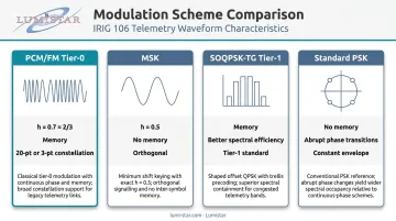
| Scheme | h | Memory | Notes |
|---|---|---|---|
| PCM/FM (Tier-0) | 0.7 (≈ 2/3) | Yes | 20-pt or 3-pt constellation |
| MSK | 0.5 | No | Orthogonal, no inter-symbol phase dependency |
| SOQPSK-TG (Tier-1) | — | Yes | Better spectral efficiency, different constellation |
| Standard PSK | — | No | Abrupt phase transitions, not constant-envelope |
Why PCM/FM Is the Standard for Aeronautical Telemetry
Historical Adoption and Current Standing
When analog FM telemetry programs transitioned to digital data in the late 1960s and early 1970s, the path of least resistance was clear: feed filtered NRZ-PCM into existing FM transmitters. No new RF hardware, no new frequency allocations, no new infrastructure. IRIG 106-15 Appendix A states that PCM/FM has been the most popular telemetry modulation method since approximately 1970 — a position it has not ceded.
Quantitative adoption breakdowns across current Tier-0 versus Tier-1/Tier-2 programs are not publicly available in authoritative sources, but qualitative statements from IRIG and ARTM literature consistently describe PCM/FM as dominant across military, commercial, and government test ranges.
What Aeronautical Telemetry Demands
Airborne telemetry environments impose specific constraints that PCM/FM addresses directly:
- Supports nonlinear (saturated) RF power amplifiers through constant-envelope modulation — a requirement linear schemes cannot meet
- Meets IRIG 106 spectral masks across L-band (1435–1525 MHz, 1755–1850 MHz), S-band (2200–2395 MHz), and C-band (4400–4940 MHz, 5091–5150 MHz), with the PCM/FM mask defined at K = −28 using h = 0.7 and a 0.7 × bit rate premodulation filter
- Operates on existing transmitters, antennas, and frequency allocations without modification
The Cost of Ignoring the Phase Modulation Framework
Programs that rely exclusively on limiter-discriminator receivers operate at a ~3.5 dB SNR disadvantage compared to what optimal detection of the same waveform can deliver. In range-limited scenarios — long-range test missions, weak signal returns, contested RF environments — that margin can be the difference between recovering valid data and losing a test point.
The phase modulation reinterpretation matters precisely because it offers a path to closing that gap without touching the transmitted signal, the frequency allocation, or the IRIG compliance status.
How the Phase Modulation Interpretation of PCM/FM Works
Step 1: PCM Bitstream and Pulse Shaping
NRZ-L encoded binary data enters a premodulation low-pass filter before reaching the modulator. Per IRIG 106-22, the standard filter is a multi-pole linear phase filter with a −3 dB corner at 0.7 × bit rate. The most common implementation is a Bessel filter (4th through 8th order), chosen because its linear phase response preserves phase characteristics during pulse shaping.
What the filter actually does to the signal:
- Smooths abrupt NRZ bit transitions into rounded frequency pulses
- Spreads the frequency pulse across L = 3 symbol times (partial-response CPM)
- Controls sideband energy to comply with the IRIG spectral mask
- Introduces controlled inter-symbol interference that the receiver must account for

Tighter filtering reduces spectral occupancy but increases ISI. IRIG Appendix A notes that the filter attenuates RF sidebands while degrading BER by only a few tenths of a dB — a favorable trade-off in practice.
Step 2: CPFSK Modulation and Phase Accumulation
The filtered baseband signal frequency-modulates the carrier. Because phase is the integral of frequency:
- A binary "1" accumulates +hπ radians over one bit period
- A binary "0" accumulates −hπ radians over one bit period
Phase accumulates continuously across bit boundaries — there are no instantaneous jumps. Over multiple bit periods, this creates a phase tree: the current phase depends on the sequence of all previously transmitted bits, not just the current one. That memory is what makes PCM/FM a richer signal than simple two-frequency FSK and what coherent detection exploits.
Step 3: Phase Approximation and Coherent Detection
That accumulated phase memory doesn't disappear at the receiver — it becomes the basis for coherent detection. Applying the h = 2/3 approximation reduces the infinite phase tree to a manageable three-state structure, which enables:
- Single-symbol CPFSK detection: Correlate against expected phase trajectories over one bit period — significant improvement over limiter-discriminator
- Multi-symbol detection: Extend correlation across multiple symbol intervals, exploiting the phase memory directly
- Optimal sequence detection: Apply Viterbi-style algorithms over the full trellis — maximum theoretical performance
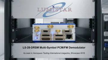
Each step up this hierarchy improves BER at the same Eb/N0. Lumistar's LS-28-DRSM series implements this full progression as firmware-selectable modes — supporting both multi-symbol PCM/FM demodulation and true legacy analog single-symbol PCM/FM. The multi-symbol implementation delivers a 2.5 dB typical Eb/N0 improvement over single-symbol detection, with no changes required to existing ground station infrastructure.
Key Factors That Affect PCM/FM Proven Performance
The detection method dominates all other factors. Moving from limiter-discriminator to multi-symbol detection matters more than any RF link optimization at typical operating SNRs. Once the detection architecture is chosen, four factors govern how close to theoretical performance you actually get:
- Modulation index accuracy: Transmitter deviation must stay near h = 0.7 (peak deviation 0.35 × bit rate). Drift shifts the phase constellation and reduces minimum Euclidean distance between symbols. Lumistar's transmitters specify FM peak deviation adjustable from 0.3 to 0.4, with 0.35 as the default, keeping the modulation index within the IRIG-specified tolerance throughout the mission.
- Pulse shaping filter: Bessel filter order and −3 dB corner frequency directly shape the phase trajectory. Incorrect filter implementation distorts the CPM phase structure that coherent receivers depend on.
- RF link budget: Constant-envelope modulation gives inherent immunity to amplitude noise, but transmit power, antenna gain, range, and receiver noise figure still govern whether received Eb/N0 clears the detection threshold for the chosen receiver architecture.
- IRIG spectral mask compliance: Programs on fixed frequency allocations cannot change their spectral footprint. The h = 2/3 reinterpretation matters operationally because it improves detection performance without altering that footprint.
Common Misconceptions and Limitations
"PCM/FM is just FM"
The transmitter is an FM modulator — but the signal it produces is a CPM waveform with phase memory, inter-symbol phase dependency, and a coherently detectable phase structure. Treating it as analog FM means applying suboptimal detection and accepting a ~3.5 dB performance penalty that the waveform itself does not impose.
"The h = 2/3 approximation changes the signal"
It does not. The approximation is applied at the receiver as a mathematical reinterpretation of the received phase trajectory. The transmitted waveform at h = 0.7 is unchanged. The h = 2/3 power spectrum is nearly identical to h = 0.7, fits within the same IRIG spectral mask, and falls within the deviation tolerance range of fielded transmitters.
"Optimal PCM/FM detection makes Tier-1/Tier-2 unnecessary"
This overstates the case. IRIG Appendix A reports occupied bandwidths of:
- PCM/FM: 1.16 × bit rate
- SOQPSK-TG (Tier-1): 0.78 × bit rate
- ARTM CPM (Tier-2): 0.56 × bit rate
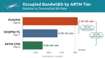
Tier-1 provides approximately 2× PCM/FM data capacity in the same bandwidth; Tier-2 provides approximately 3×. For programs managing multiple simultaneous channels, or operating in severely bandwidth-constrained allocations, SOQPSK-TG or multi-h CPM remain the right architectural choice despite the BER advantage of optimally decoded Tier-0.
Implementation Complexity
Multi-symbol and optimal sequence detection require substantially more signal processing overhead than a limiter-discriminator. The prototype hardware developed during the ARTM program implemented digital PCM/FM recovery algorithms on a single circuit card, supporting data rates from 0.5 to 11 Mbps.
Modern FPGA-based receivers like the LS-28-DRSM extend this to 30 Mbps in production hardware — but the computational overhead is real, and programs should factor it into system design.
Conclusion
Understood as a ternary phase modulation process with h ≈ 2/3, PCM/FM is a coherently detectable, constant-envelope signal that outperforms both ARTM Tier-1 and Tier-2 in raw error rate — while operating within the same spectral mask that has governed aeronautical telemetry since 1970. The waveform hasn't aged out of relevance; the receivers processing it have simply underperformed what the signal allows.
For programs on fixed frequency allocations where infrastructure changes are impractical, this matters directly. The phase modulation reinterpretation offers ~3.5 dB of recoverable link margin through receiver architecture alone, with no change to the transmitter, no new frequency coordination, and full IRIG 106 compliance.
The engineering decision that determines whether that margin is realized is receiver selection. Hardware that supports firmware-selectable multi-symbol detection (rather than locking programs into legacy limiter-discriminator performance) is the specification detail worth examining before the next procurement. Lumistar's demodulator products support this capability through firmware-based personalities, allowing receiver architecture to be updated without replacing existing hardware.
Frequently Asked Questions
What is the difference between PCM and FM?
PCM (Pulse Code Modulation) is a digital encoding method that converts analog signals into binary data. FM (Frequency Modulation) is an RF transmission method that varies carrier frequency to carry information. In PCM/FM telemetry, the PCM bitstream is used to frequency-modulate a carrier, combining both into a single transmission standard defined under IRIG 106.
Is PCM still used today?
Yes. PCM/FM (ARTM Tier-0) is the most widely deployed telemetry modulation standard in aeronautical flight test globally, used across military, commercial, and government test ranges under IRIG 106. It has been the dominant method since approximately 1970.
What is the bandwidth of a PCM/FM signal?
Per IRIG 106-15 Appendix A, filtered NRZ PCM/FM with h = 0.7 and a 0.7 × bit rate premodulation filter has a 99% bandwidth of approximately 1.16 × bit rate. The IRIG spectral mask governs permissible bandwidth for telemetry applications, using K = −28 for binary NRZ PCM/FM.
What is the bandwidth of PCM itself?
PCM is a baseband digital encoding format; it does not inherently have an RF bandwidth. When transmitted as PCM/FM, RF bandwidth is determined by the modulation index, bit rate, and pulse shaping filter — governed by IRIG 106 spectral masks.
Which is better, PCM or delta modulation?
Both convert analog signals to digital, but PCM offers higher fidelity through multi-bit quantization and wider dynamic range. Delta modulation tracks signal changes using only one bit per sample interval. In telemetry, PCM/FM is the IRIG-standardized approach due to its superior data integrity, flexibility, and established standards compliance.
Is PCM the same as PWM?
No. PCM (Pulse Code Modulation) encodes signal amplitude as multi-bit binary words sampled at regular intervals. PWM (Pulse Width Modulation) represents information by varying pulse duration. PCM is used for digital data encoding; PWM is common in power control and certain analog signal applications.