Introduction
FM has been a cornerstone of RF communications since the 1930s — and it remains just as relevant today in aeronautical telemetry, PCM/FM data links, and flight test ground stations. What has changed is how FM signals are generated and recovered. Where analog discriminators and voltage-controlled oscillators once handled the heavy lifting, modern systems use software-configurable DSP algorithms running on FPGAs and SDR platforms.
That shift matters because DSP implementations expose every design parameter explicitly: sampling rate, frequency deviation constant, FIR filter tap count, PLL loop bandwidth. Each of these choices has a direct consequence on output quality — noise floor, distortion, lock behavior, and demodulated signal accuracy all trace back to specific configuration decisions.
Understanding those decisions is what this guide is for. It covers the discrete-time mechanics of FM modulation, the three primary DSP demodulation methods, critical parameter decisions, and the implementation errors that most commonly degrade output quality.
Key Takeaways
- FM modulation in DSP encodes the message signal into instantaneous frequency via a discrete-time phase accumulator
- Three demodulation methods exist: delay-conjugate product, atan2 + FIR differentiator, and Phase-Locked Loop (PLL)
- The atan2 + FIR differentiator offers the best SNR-to-complexity tradeoff for most applications
- Sampling rate, frequency deviation constant, FIR tap parity, and PLL loop bandwidth each directly affect demodulation accuracy
- PCM/FM per IRIG 106 specifies optimum peak deviation at 0.35× bit rate with modulation index h = 0.7 — these must be matched at the receiver
How FM Modulation Works in DSP
FM is angle modulation. The message signal shifts the instantaneous frequency of the carrier rather than its amplitude, which means the carrier envelope stays constant regardless of the message content. That constant-envelope property is one reason FM dominates telemetry applications — power amplifiers can operate at saturation, and the signal holds up well against noise.
The continuous-time FM signal equation is:
s(t) = Aₙ cos[2πfₙt + 2πkf ∫m(τ)dτ]
where the instantaneous frequency is fᵢ(t) = fₙ + kf·m(t). Frequency is the derivative of phase, so encoding the message into instantaneous frequency requires integrating the message to produce a time-varying phase term. That integral is what all three demodulation methods are trying to undo.
Frequency Deviation and Modulation Index
The frequency deviation constant kf scales message amplitude to instantaneous frequency shift. Peak frequency deviation Δf = kf × Aₘ describes how far the carrier swings from center. The modulation index β = Δf/B (where B is message bandwidth) classifies the signal:
- Narrowband FM (β << 1): bandwidth close to 2×B, SNR performance similar to AM
- Wideband FM (β >> 1): bandwidth ≈ 2Δf, substantially better output SNR
- High β signals: output SNR scales approximately as 3β² relative to an equivalent AM link
For IRIG 106-compliant PCM/FM, the optimum peak deviation is 0.35× the bit rate R, with h = 0.7 and a premodulation filter bandwidth of 0.7R.
Carson's Rule and Bandwidth
Carson's rule estimates FM signal bandwidth as:
BFM ≈ 2(Δf + B) = 2(β + 1)B
This approximation captures roughly 98% of FM spectrum power and is useful for initial channel planning. For telemetry compliance, IRIG 106 uses stricter metrics: 99% power bandwidth (B99%) and -25 dBm bandwidth. For NRZ PCM/FM with 0.7R premodulation filtering and 0.35R peak deviation, B99 ≈ 1.16R.
FM trades bandwidth for noise performance. Wideband FM requires more channel allocation than AM, but the SNR gains justify that tradeoff in most telemetry link budgets.
Discrete-Time FM Modulator Architecture
Converting the continuous-time integral to discrete time produces a recursive accumulator:
θ[n] = θ[n−1] + 2π·kf·Ts·x[n−1]
This accumulator is the heart of a Numerically Controlled Oscillator (NCO). The accumulated phase index drives a cosine/sine look-up table (LUT) to synthesize the FM waveform. Add a DAC and you have a Direct Digital Synthesizer (DDS), the standard architecture in modern telemetry transmitters.
A complete DSP-based FM modulator chains four components:
- Phase accumulator — integrates the frequency-modulated input sample by sample
- Cosine/sine LUT — maps accumulated phase to a synthesized waveform
- DAC — converts the digital waveform to an analog output signal
- Carrier mixing stage — upconverts the baseband signal to the RF center frequency
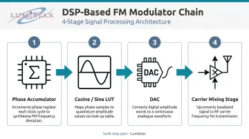
The output is a complex exponential at carrier frequency fₙ with a time-varying phase component.
All three demodulation methods covered below operate on the baseband I/Q signal, recovered by multiplying the received signal with e^(−j2πfₙnTs) to remove the carrier.
The Three DSP Methods for FM Demodulation
FM demodulation in DSP means recovering the message signal from the instantaneous phase of a complex baseband signal. The three methods differ in when phase extraction and differentiation occur — each with distinct trade-offs in complexity, SNR, and hardware requirements.
Method 1: Delay-Conjugate Product (Differentiate Then Access Phase)
This is the simplest approach and the one implemented in GNU Radio's Quadrature Demod block:
v[n] = z[n] · z*[n−1] y[n] = arg(v[n])
Multiplying the current sample by the complex conjugate of the previous sample produces a value whose argument equals the phase difference between consecutive samples. Scaling by 1/(2π·kf·Ts) recovers the message signal.
At high sample rates, the imaginary part of v[n] approximates the phase difference, bypassing the atan2 computation entirely. This makes Method 1 extremely fast and easy to implement.
Trade-off: The first-difference operation is a crude differentiator with poor high-frequency noise performance. SNR is lower than Methods 2 and 3.
Method 2: Access Phase Then Differentiate (atan2 + FIR Differentiator)
Two variants exist here:
Variant A — atan2 then FIR:
- Extract instantaneous phase: θ[n] = atan2(Q[n], I[n])
- Unwrap the phase sequence
- Apply an optimized FIR differentiator h[n] to recover the message
Variant B — I/Q derivative form (no atan2):
θ̇ = (I·(dQ/dt) − Q·(dI/dt)) / (I² + Q²)
Both variants outperform Method 1 in SNR because the differentiator acts on phase rather than the full complex signal, and a well-designed FIR can be shaped for flat frequency response across the signal band.
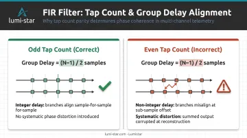
Critical implementation constraint: For Variant B, the FIR differentiator must have an odd number of taps. This ensures the group delay (N−1)/2 is an integer number of samples, keeping both branches of the demodulator time-aligned. Misalignment produces systematic distortion in the recovered signal.
Variant A is well-suited to FPGA pipelines where CORDIC-based atan2 hardware runs at high clock rates. Padilla (2011) reports a Virtex-4 feed-forward arctangent-differentiator architecture achieving 297.8 MHz maximum clock rate.
Unlike the open-loop architectures above, Method 3 closes the loop around the signal entirely.
Method 3: Phase-Locked Loop (PLL)
A discrete-time PLL tracks the FM signal's instantaneous frequency through a feedback loop — phase detector, loop filter, then NCO. When locked, the NCO control signal mirrors the message signal, and demodulation happens as a byproduct of phase tracking. At sufficient oversampling rates, PLL SNR matches Method 2, but only with careful parameter tuning.
Three parameters control PLL behavior:
- Loop bandwidth: Must be wide enough to track the full frequency deviation, narrow enough to suppress noise
- Phase-per-sample limits: Set by the ratio of frequency deviation to sample rate — these bound the NCO's operating range
- Output scaling: Amplitude normalization is required because the loop filter output amplitude depends on the NCO gain
Comparing the Three Methods
| Method | Complexity | SNR | Best Use Case |
|---|---|---|---|
| Delay-conjugate | Very low | Lowest | SDR prototyping, GNU Radio, adequate-SNR links |
| atan2 + FIR | Medium | Best | Most production DSP implementations |
| PLL | High | Similar to Method 2 | Noisy environments with careful tuning |
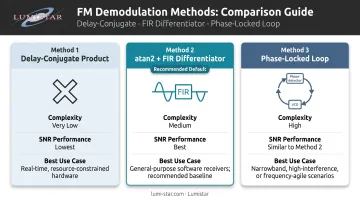
For most telemetry and flight test DSP implementations, the atan2 + FIR differentiator approach (Method 2) is the recommended default.
Key Parameters That Affect FM DSP Results
Even a correctly structured demodulator produces degraded output if key parameters are misconfigured. These are the primary control variables.
Sampling Rate
The sample rate must satisfy Nyquist with respect to the FM signal bandwidth per Carson's rule. Beyond Nyquist compliance, a higher sample rate:
- Reduces phase estimation error in the delay-conjugate method
- Keeps consecutive sample-to-sample phase advance well below 180° — at exactly Nyquist, successive vectors can advance 180°, creating phase ambiguity
- Enables the imaginary-part approximation shortcut for atan2 in Method 1
Oversampling by 4× or more significantly reduces phase-angle error in polar discriminators. The commonly cited "6–10× Nyquist" guideline appears frequently in engineering practice but is not verified by a published standard. Treat it as a design heuristic, not a specification.
Frequency Deviation Constant and Modulation Index
The deviation constant k_f directly scales recovered message amplitude. If set incorrectly:
- Output will be scaled (too small or too large)
- Clipping occurs if the demodulator underestimates peak deviation
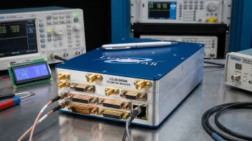
For IRIG 106-compliant PCM/FM, deviation and modulation index are standardized (h = 0.7, peak deviation = 0.35R) and must be matched at the receiver. Lumistar's LS-35-R and LS-28-DRSM receivers configure FM peak deviation in the 0.3–0.4 range with a default of 0.35, matching IRIG 106 requirements directly.
FIR Differentiator Design
For Method 2, the FIR differentiator quality determines demodulation fidelity:
- Odd tap count is mandatory for the I/Q derivative variant (ensures integer group delay)
- Flat frequency response across the message bandwidth is required for output accuracy
- Higher tap counts improve frequency response but increase computational cost
The group delay introduced by the FIR must be exactly compensated in the non-differentiated signal branch. One sample of mismatch produces systematic distortion across all recovered frequencies.
Phase Unwrapping
When using atan2, the function wraps output to ±π. Differentiating wrapped phase without unwrapping first produces large spurious jumps at the ±π boundary — these appear as broadband noise spikes in the demodulated output.
The fix options:
- Explicit phase unwrapping before differentiation
- Adjacent-sample conjugate multiplication (Method 1), which inherently returns the principal phase difference within ±π for adequately oversampled signals
What You Need Before Implementing FM DSP
Implementation requirements depend significantly on the target platform.
Hardware and Software Platform Requirements
| Platform | Strengths | Limitations |
|---|---|---|
| FPGA | Pipelined CORDIC atan2, parallel FIR, high throughput | Less flexible for algorithm changes |
| DSP processor | Flexible, easy to modify | Sequential execution limits throughput |
| SDR (e.g., GNU Radio) | Rapid prototyping, modular blocks | Latency, not real-time for high-rate links |
Minimum requirements across all platforms:
- Complex baseband (I/Q) signal at an adequate sample rate
- Multiply-accumulate (MAC) throughput matching the signal data rate
- Trigonometric functions or CORDIC hardware for atan2
An FPGA-based FM demodulator has demonstrated 2× throughput over a DSP processor implementation at equivalent signal quality, making FPGAs the better fit for multi-channel or high-rate telemetry ground stations.
Lumistar's LS-28-DRSM series and LS-35-R receivers implement all-digital DSP demodulation on Xilinx Virtex-5 FPGA platforms, supporting PCM/FM data rates from 1 kbps to 30 Mbps. Over 40,000 automatically optimized IF bandwidths are pre-configured, removing the need to manually tune FIR parameters for most IRIG 106 PCM/FM configurations.
Input Signal Conditions
Before demodulation begins, verify:
- Signal is downconverted to complex I/Q baseband (or 70 MHz IF for hardware receivers)
- Carrier frequency offset is corrected
- Normalize amplitude for methods requiring unit-magnitude input
- IRIG 106 deviation parameters match receiver configuration
Common Mistakes When Implementing FM DSP
Ignoring Phase Wrapping
The most common implementation error is applying atan2 to extract phase, then differentiating with floating-point subtraction without unwrapping. Phase jumps at the ±π boundary produce broadband noise spikes that destroy demodulation quality.
Use either explicit phase unwrapping before differentiation, or Method 1's conjugate multiplication, which handles the ±π boundary inherently.
Misaligned FIR Branches in the I/Q Derivative Method
When using Method 2's I/Q derivative variant, the group delay from the FIR differentiator must be exactly matched by a corresponding delay on the non-differentiated branch. Engineers frequently overlook this. An even number of taps makes the group delay non-integer, which cannot be compensated by a simple delay element — use an odd tap count.
Incorrect PLL Loop Bandwidth
Misconfigured PLL loop bandwidth is a consistent source of failure:
- Too narrow: the loop cannot track the full FM deviation swing
- Too wide: excess noise enters and the loop risks instability
The correct value scales with the ratio of frequency deviation to sample rate. Recalculate it whenever the sample rate changes — using the rate entering the PLL block, not the system-wide sample rate upstream.
Frequently Asked Questions
What is the difference between narrowband FM and wideband FM in DSP implementations?
Narrowband FM (β << 1) has bandwidth near 2× the message bandwidth, behaves similarly to AM, and is simple to demodulate. Wideband FM (β >> 1) occupies bandwidth approximately equal to 2Δf, delivers better output SNR, and is standard for high-fidelity audio and PCM/FM telemetry — at the cost of wider channel allocation and more careful DSP parameter tuning.
Why is the delay-conjugate discriminator so widely used despite its SNR limitations?
One complex conjugate, one multiplication, one atan2 — the entire demodulator fits in a handful of operations, which is why it's the default in GNU Radio's Quadrature Demod block. For applications where received SNR is adequate, the computational simplicity and single-pass architecture outweigh the noise penalty compared to Method 2.
Does FM demodulation using DSP require a constant-amplitude input signal?
The delay-conjugate (Method 1) and atan2 + FIR differentiator (Method 2a) approaches are relatively insensitive to amplitude variations since information is encoded in phase. The I/Q derivative variant (Method 2b) and PLL-based demodulators require amplitude normalization (dividing I/Q samples by signal magnitude) to function correctly.
What sample rate is needed for FM demodulation in a DSP system?
The minimum is above Nyquist for the FM bandwidth per Carson's rule, but oversampling by 4× or more is practical standard: it reduces phase estimation error, keeps consecutive phase increments well below 180°, and enables the imaginary-approximation shortcut for the delay-conjugate method. The "6–10×" figure is a widely used engineering heuristic, not a codified standard.
How does FPGA implementation of FM demodulation compare to a DSP processor?
An FPGA implementation with pipelined CORDIC atan2 and parallel FIR differentiators has demonstrated 2× throughput versus a sequential DSP processor at equivalent signal quality. For high-speed or multi-channel telemetry ground stations, FPGAs are the preferred platform. DSP processors offer more flexibility when algorithm parameters need frequent changes.
How is FM used in aeronautical telemetry and IRIG 106 systems?
PCM/FM has dominated aeronautical telemetry since approximately 1970. IRIG 106 specifies FM modulation of digital data onto an RF carrier with optimum peak deviation at 0.35R and modulation index h = 0.7. Lumistar's LS-28-DRSM performs all demodulation digitally, replacing legacy analog discriminators while maintaining full IRIG 106 compliance.