Introduction
Picture a ground station receiving telemetry from a test aircraft mid-flight. The data looks clean on paper — until you notice the bit error rate climbing. The culprit isn't noise or interference. It's timing. The receiver's internal clock has drifted just a fraction out of phase with the transmitter, and now bits are being sampled at the wrong moment. Critical flight parameters are corrupted before they ever reach the display.
This isn't an edge case. It's one of the most common failure modes in digital communication links, and it's exactly what bit synchronization exists to prevent.
This article covers the fundamentals engineers and systems integrators need: what bit synchronization is, how clock recovery works, the main synchronization methods, how it differs from frame synchronization, and why it's especially demanding in aeronautical telemetry environments. Whether you're working with PCM telemetry, IRIG 106 flight test systems, or any high-speed digital data link, understanding these fundamentals is the first step toward reliable data acquisition.
Key Takeaways
- Bit synchronization aligns a receiver's internal clock to the incoming bitstream so each bit is sampled at the correct moment
- Clock recovery uses signal transitions and a Phase-Locked Loop (PLL) to continuously track transmitter timing
- Poor sync drives up Bit Error Rate (BER) — IRIG 106 Chapter 4 caps bit jitter at ±0.1 bit intervals with 0.1% rate tolerance
- Frame synchronization cannot work until bit sync is established first
- Flight test demands fast acquisition, wide pull-in range, and tracking through dropouts and Doppler shifts
What Is Bit Synchronization and Why Does It Matter
The Core Problem
Every digital receiver faces the same fundamental challenge: the transmitter has its own clock, and the receiver has its own clock. They're never perfectly aligned. Independent oscillators drift over time due to temperature changes, vibration, and aging. Propagation delays shift the signal's timing further. By the time a bitstream arrives at the receiver, its timing is slightly different from what the transmitter sent — and that difference grows continuously.
Bit synchronization (also called clock synchronization or bit timing recovery) is the process by which the receiver continuously aligns its internal clock to match the incoming bitstream. The goal is to sample each bit at exactly the right moment.
The Sampling Window
For reliable data recovery, the receiver must sample each bit at the center of the bit period — the point of maximum signal-to-noise margin. Even a small timing offset pushes sampling toward the bit edges, where intersymbol interference and noise degrade the decision.
This is captured by the Bit Error Rate (BER), the primary metric for synchronization quality. IRIG 106 Chapter 4 quantifies acceptable limits for flight test telemetry: bit rate must not differ from nominal by more than 0.1%, and bit jitter must not exceed ±0.1 bit interval. Exceed those thresholds and data integrity degrades rapidly.
Synchronization Is Continuous, Not One-Time
A common misconception is that bit sync happens once at link acquisition. In practice, clock drift is ongoing — a constant fractional frequency offset between two oscillators accumulates timing error throughout the transmission. The synchronizer must continuously track and correct this drift for the entire duration of the link, operating as a closed-loop control system rather than a one-time alignment step.
The primary sources of this ongoing drift include:
- Oscillator aging — independent clocks diverge gradually over time
- Temperature variation — thermal changes alter oscillator frequency
- Vibration — mechanical stress shifts timing in airborne and range environments
- Propagation delay — signal travel time introduces additional offset at acquisition
How Bit Synchronization Works: The Clock Recovery Process
Extracting Timing from the Signal
Most practical communication systems send data and clock over the same channel — there's no separate timing wire. So the receiver must extract timing information directly from the incoming data signal itself.
The starting point is transition detection. The receiver monitors the signal for edges (0-to-1 or 1-to-0 changes). These transitions occur at bit-period boundaries and carry the timing information the synchronizer needs. The choice of line code directly affects how many transitions are available:
- NRZ-L produces transitions only when the bit value changes — long runs of identical bits generate no transitions
- Biphase-L (Manchester) guarantees at least one transition per bit period, making clock recovery far more reliable
- IRIG 106 permits NRZ-L, NRZ-M, NRZ-S, Bi-Phase-L, Bi-Phase-M, Bi-Phase-S, and RNRZ-L for PCM telemetry
The Phase-Locked Loop
The PLL is the core hardware mechanism for clock recovery. Its operation follows a closed feedback loop:
- Phase detector compares transitions in the incoming signal against the phase of a locally generated clock
- Loop filter processes the phase error signal, setting the balance between tracking speed and noise rejection
- Voltage-Controlled Oscillator (VCO) adjusts its frequency based on the filtered error until the local clock is phase-locked to the incoming data
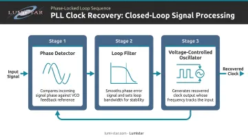
The loop bandwidth of the filter is a critical design parameter. Wider bandwidth means faster response to phase changes but more susceptibility to jitter and noise. Narrower bandwidth rejects noise better but tracks changes more slowly. IRIG 106 Chapter 2 states that bit synchronizer loop bandwidth should be designed for optimal phase-noise filtering and symbol tracking performance. In practice, loop bandwidths are commonly set between 1% and 5% of the bit rate — wider for highly dynamic platforms, narrower for stable, high-SNR links.
Sampling and Buffering
Once the recovered clock is phase-locked, the receiver uses it to sample the incoming signal at the optimal point within each bit period — typically the center, where the signal is most stable. Sampling at the wrong phase increases bit error rate even when the clock frequency is correct.
Sampled values are written into a receive buffer for downstream processing. The downstream chain typically includes:
- Frame synchronization: locating the sync pattern that marks the start of each PCM frame
- Decommutation: extracting individual parameters from their assigned frame positions
- Data display and archiving: routing engineering unit values to real-time displays and recording systems
Types of Bit Synchronization Methods
Bit synchronizers fall into two broad categories: open-loop methods derive timing by processing received signal characteristics without feedback; closed-loop methods use continuous feedback to correct clock timing based on measured error.
Closed-Loop Methods
Early-Late Gate Synchronizer One of the most widely used closed-loop techniques. The receiver computes signal energy in an "early" window and a "late" window on either side of the estimated bit center. If the windows are unequal, the clock shifts to rebalance them. This approach is particularly reliable in noisy channels because it uses energy integration rather than relying on sharp signal edges.
Data Transition Tracking Loop (DTTL) A feedback loop that uses actual data transitions — rather than energy windows — to drive clock correction. It performs well when the data stream contains frequent transitions and is commonly used in telemetry demodulators. Research documented in IEEE Xplore (document 225481) examined how signal transition variation affects DTTL performance, including clock jitter effects at the symbol synchronizer.
Open-Loop Methods
Squaring Loop The received signal is squared to produce a periodic component at the bit rate, which is then extracted with a bandpass filter and used directly as the clock. The approach is simple to implement but sensitive to signal quality — noise and distortion degrade the spectral line that the filter needs to isolate.
Modern Implementation
Today's digital bit synchronizers implement these algorithms in FPGA firmware or DSP, rather than analog circuitry. Firmware-based synchronizers can be reconfigured without hardware changes for:
- Different data rates
- PCM code formats
- Loop bandwidth settings
This flexibility is particularly valuable in multi-mission telemetry systems where operational requirements shift between programs.
Bit Synchronization vs. Frame Synchronization
Bit synchronization and frame synchronization operate at different levels of the same hierarchy, and the distinction matters.
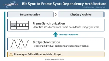
Bit synchronization answers: where does each individual bit begin and end? It operates on the raw signal and produces a clean, timed bitstream.
Frame synchronization answers: which group of bits forms a complete data frame? It operates on the already-synchronized bitstream, searching for a known pattern embedded by the transmitter.
How Frame Sync Works
The transmitter inserts a fixed frame sync word at regular intervals in the data stream. The receiver runs a state machine that searches the synchronized bitstream for this repeating pattern. Once found, the receiver knows where each frame starts and can correctly assign measurement values to their parameters.
Per IRIG 106 Chapter 4, PCM telemetry minor frame sync words must be 16 to 33 bits long, with patterns chosen from Appendix 4-A to minimize false synchronization probability.
Minor frames can be up to 8,192 bits (Class I) or 16,384 bits (Class II). Major frames extend this structure further, allowing up to 256 minor frames — which means a misidentified sync word propagates errors across a substantial data block.
The Dependency
Without solid bit synchronization, frame synchronization fails. A single misaligned bit shifts every subsequent bit in the frame search, causing the sync word detector to miss or misidentify the pattern. Bit sync is the prerequisite layer. Frame sync, time correlation, and data decommutation all sit on top of it — if the foundation slips, the entire chain breaks down.
Common Challenges in Bit Synchronization
Jitter
Jitter is the primary enemy of any bit synchronizer: rapid, short-term variations in clock edge timing that blur the boundary between bit periods. It's measured in RMS picoseconds or as a fraction of the bit period (unit intervals). As jitter increases, the eye diagram's horizontal opening narrows, reducing the timing margin available for reliable sampling.
IRIG 106's ±0.1 bit interval jitter limit exists precisely because flight test telemetry systems push data rates high enough that small timing variations directly affect BER. Eye diagram analysis is the standard diagnostic tool — the horizontal opening of the eye directly shows available timing margin.
Low Transition Density
When a data stream contains long runs of identical bits, the PLL has no transitions to lock onto. The recovered clock drifts, and timing error accumulates. IRIG 106 Chapter 4 recommends a maximum gap of 64 bit intervals between transitions for reliable synchronization.
Two practical solutions:
- Biphase encoding guarantees at least one transition per bit period
- Pseudo-randomization (RNRZ-L) scrambles the data to break up repetitive patterns — IRIG 106 Chapter 2 explicitly recommends a pseudo-randomizer after LDPC encoding because LDPC codes do not guarantee sufficient transitions on their own
Doppler-Induced Frequency Shift
Unlike data-pattern problems, Doppler shift is a physics-level challenge: the aircraft's velocity relative to the ground station creates a frequency offset that the bit synchronizer reads as a clock rate error. Fast acceleration during maneuvers can push the apparent bit rate outside a narrow-bandwidth synchronizer's tracking range entirely.
Flight test bit synchronizers must handle two related requirements:
- Pull-in range (the frequency offset they can acquire from) — wide enough to capture a fast-moving platform on initial lock
- Tracking bandwidth — sufficient to follow dynamic rate changes through aggressive maneuvers

Programmable loop bandwidth addresses both: operators select wider bandwidth for high-dynamics phases, then tighten it during stable cruise to reduce noise.
Bit Synchronization in Aeronautical Telemetry and Flight Test Systems
Aeronautical telemetry links combine everything that makes bit synchronization difficult: high data rates, rapidly changing geometry, multipath fading, and signal dropouts during aircraft maneuvers. A synchronizer that performs well in a benign lab environment can fail to maintain lock through a high-g pull or a brief antenna blockage.
IRIG 106 Compliance
IRIG 106, maintained by the Range Commanders Council Telemetry Group, is the governing standard for PCM telemetry at U.S. flight test ranges. Chapter 4 defines the pulse train structure, supported code formats, timing tolerances, and frame synchronization requirements that compliant systems must meet. Chapter 2 provides receiver system performance requirements including phase noise limits — receivers must keep phase noise below -103 dBc/Hz from 1 MHz to one-fourth the bit rate for rates above 4 Mbps.
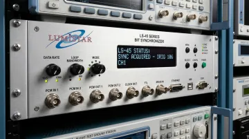
Meeting these requirements demands hardware built specifically for the flight test environment. Lumistar's bit synchronizer product families — including the LS-45 series and the integrated LS-28-DRSM and LS-68-M systems — are designed for IRIG 106 Class I and Class II compliance across the full range of permitted PCM formats (NRZ-L/M/S, Bi-Phase L/M/S, Miller codes, and RNRZ variants).
Proven Performance Specifications That Matter in Flight Test
Key specifications across Lumistar's LS-45 series bit synchronizers:
| Parameter | Specification |
|---|---|
| Data rate range | 100 bps to 45 Mbps (NRZ); 100 bps to 22.5 Mbps (Bi-Phase/Miller) |
| Pull-in range | ±5% of bit rate |
| Mean acquisition time | <100 bits at 1% loop bandwidth |
| BER degradation (NRZ <20 Mbps) | <1 dB from theoretical |
| Sync hold through dropout | Up to 245 bits lost per 1,024 (NRZ ≤5 Mbps) |
| PLL loop bandwidth | Programmable, 0.001% to 5% |
LS-28-DRSM and LS-68-M: Extended Capabilities
The LS-28-DRSM builds on the LS-45 foundation with features suited to diversity reception and multi-channel missions:
- Three independent simultaneous bit synchronizers (CH1, CH2, and combined diversity outputs)
- Built-in BER readers with data rates up to 60 Mbps for advanced modulation formats
- Full software configuration (loop bandwidth, code format, input impedance, polarity) via Ethernet, USB, or RS-232 — no operating system required
The LS-68-M takes a different approach: a complete baseband processing ground station — bit sync, frame sync, decommutation, and display — in a portable or 1U rack-mount package. Configuration is handled through firmware licensing rather than hardware swaps. One platform can run as three PCM Frame Synchronizer/Decommutators for one mission, then reconfigure for a different combination on the next.
This firmware-based architecture — built on FPGA platforms like the Xilinx Virtex-5 used in the LS-35-R — is what makes field reconfiguration practical. New code formats and DSP algorithm updates arrive as firmware or license files, not hardware replacements.
Frequently Asked Questions
What is bit synchronization in digital communication?
Bit synchronization is the process of aligning a receiver's internal clock to the timing of an incoming bitstream so each bit is sampled at the correct moment. Without it, the receiver samples at the wrong phase of each bit period, causing bit errors and data corruption.
How does bit synchronization work?
The receiver detects transitions in the incoming signal and feeds them into a Phase-Locked Loop (PLL), which continuously adjusts a local oscillator until it matches the transmitter's timing. Once phase-locked, this recovered clock drives precise sampling of each bit.
What are the different types of bit synchronization methods?
There are two main categories: open-loop methods and closed-loop methods. Open-loop approaches (such as squaring loop filters) derive a clock from the signal's spectral properties, while closed-loop methods — including Early-Late Gate and Data Transition Tracking Loops — use continuous feedback to correct timing error.
What is the difference between bit synchronization and frame synchronization?
Bit synchronization identifies the boundaries of individual bits. Frame synchronization builds on that foundation to identify boundaries of structured data frames using an embedded sync pattern — it cannot function without reliable bit sync first.
What is a bit clock?
A bit clock is a periodic signal whose frequency equals the data bit rate. In a synchronized receiver, the bit clock is phase-aligned with the transmitter's timing so that exactly one bit is sampled during each clock cycle.
What are examples of synchronization in digital communication?
Common examples include:
- Bit synchronization in PCM telemetry links
- Frame synchronization in IRIG 106 flight test data streams
- Network synchronization in SONET/SDH systems
- Packet-level timing via IEEE 1588 Precision Time Protocol (PTP)