This post is written for aeronautical flight test engineers and range operators who need to understand how real-time antenna tracking works, what the core system components do, and how to match tracking method to mission profile. It covers the tracking methods used on modern test ranges, the key specifications that matter, and how a tracked antenna integrates with the downstream telemetry ground station.
Key Takeaways
- Aircraft and missile targets generate high, unpredictable angular rates — tracking them requires closed-loop servo systems, not pre-programmed pointing
- Monopulse is the preferred tracking method for high-dynamics targets; GPS-aided pointing serves as both a predictive aid and a fallback during signal fades
- Modern flight test pedestals support rates around 20 deg/s with 20 deg/s² acceleration; large fixed-range antennas typically top out near 10 deg/s
- Beamwidth narrows with aperture and frequency — a 4.6 m dish at S-band produces only a 2.0° 3 dB beamwidth, leaving almost no pointing tolerance
- Tracking receiver outputs (AGC, AM) feed directly into both the pedestal servo and the telemetry demodulator chain
What Is a Real-Time Antenna Tracking System?
A real-time antenna tracking system is a closed-loop electromechanical assembly that continuously repositions an antenna's azimuth and elevation axes to keep the beam aligned with a target in motion.
The feedback loop works in three steps: the tracking receiver detects an angle-error signal derived from the received RF, the antenna control unit (ACU) processes that error and calculates a corrective command, and the servo drive repositions the pedestal — completing the cycle within milliseconds, throughout the entire flight.
The key distinction from programmatic tracking is that real-time tracking reacts to measured position error, not a pre-loaded flight path. Programmatic or ephemeris-based tracking works for predictable assets like geostationary satellites, where the trajectory is known to arc-second precision days in advance. For test vehicles — where trajectory is deliberately unpredictable and deviations can exceed the antenna's beamwidth in fractions of a second — only closed-loop feedback keeps the beam on target.
Primary use cases within the aeronautical test range environment include:
- Fixed-wing and rotary-wing aircraft under flight test
- Unmanned aerial vehicles (UAVs) at all speed classes
- Missiles, rockets, and hypersonic vehicles
- Any target operating under IRIG-106 telemetry standards where uninterrupted telemetry data reception is required
Why Airborne Targets Demand Real-Time Precision
The Angular Rate Problem
Geostationary satellites sit at roughly 35,000 km altitude and move at angular rates so slow they're essentially stationary from a ground antenna's perspective. A low-flying test aircraft, by contrast, can pass almost directly overhead at high speed — producing angular rates the servo must match in real time.
Documented flight test data shows the magnitude of this requirement:
| Pedestal / System | Angular Rate | Acceleration |
|---|---|---|
| Safran SPARTE 500 (modern flight test) | 20 deg/s | 20 deg/s² |
| Western Test Range 35 ft autotrack antenna | 10 deg/s | 5 deg/s² |
| Western Test Range 80 ft antenna | 10 deg/s (both axes) | — |
| Manual quad-helix (acquisition/slew) | 30 deg/s | — |
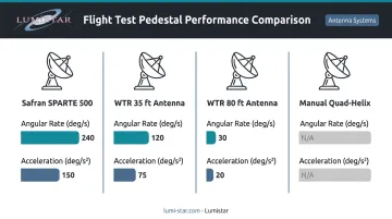
Sources: Safran SPARTE 500, Western Test Range Handbook
These aren't universal minimums — the right requirement depends on target altitude, slant range, and flight profile. But the 20 deg/s class represents a well-documented modern benchmark for precision flight test telemetry tracking.
Beamwidth and Pointing Budget
Narrow-beam antennas are used in flight test telemetry specifically for link margin — higher gain means you can maintain a usable data link at longer ranges. But gain and beamwidth trade directly against each other. Safran's published data for S-band (2.3 GHz) dishes illustrates this:
- 4.6 m dish: 2.0° 3 dB beamwidth
- 5.5 m dish: 1.6° 3 dB beamwidth
A pointing error of even 1° on a 5.5 m dish can push the target outside the half-power beamwidth, dropping received signal power significantly. Higher frequencies and larger apertures tighten this tolerance further. The Safran SPARTE 500 documents ≤0.1° tracking accuracy and 0.07°/deg/s² acceleration lag — showing just how little pointing error budget exists in practice.
Latency, Maneuvers, and Multipath
Every link in the control loop adds latency: signal detection, angle-error extraction, ACU processing, servo command, and mechanical response. The cumulative delay must stay small enough that at maximum angular rate, pointing error remains inside the half-power beamwidth. No universal latency budget exists — the calculation is vendor- and procurement-specific — but exceeding it means losing lock at the worst possible moment.
Test vehicles also execute abrupt maneuvers that break the assumptions of simple predictive models. A high-bandwidth servo with a Kalman filter-based controller handles these better than a pure reactive PID loop, because it can predict target motion between error updates rather than waiting to observe the deviation.
Near-ground flight and low elevation angles add another complication: multipath. Reflected signals from terrain can corrupt the angle-error signal, causing the antenna to steer toward a false source. IRIG-106 includes empirical multipath channel models for both land and water environments — a reminder that RF signal quality, not just mechanical speed, constrains tracking performance.
Tracking Methods for Fast-Moving Airborne Targets
Monopulse (Simultaneous Lobing)
Monopulse is the dominant method in aeronautical flight test tracking, and it's easy to see why. By comparing amplitude or phase across multiple feed elements simultaneously, monopulse derives azimuth and elevation error from a single received pulse without dwell time, scanning, or signal modulation.
Both the Western Test Range and Safran document monopulse as their autotrack method: the WTR uses fixed-scan monopulse RF electronics, while Safran's SPARTE 500 uses an 8-dipole monopulse feed with 1000 Hz sequential conical modulation (SCM) tracking. The instantaneous error derivation is precisely what makes monopulse appropriate for high-dynamics targets. With no scan period, a fast-maneuvering vehicle can't outpace the correction window.
Trade-offs: monopulse feeds are mechanically complex and more expensive than single-channel alternatives.
Conical Scan
Conical scanning generates a periodic amplitude-modulated error signal by rotating or nutating the beam around the boresight. The method works, but introduces a time lag proportional to the scan rate. Fast maneuvers occurring within one scan cycle go uncorrected until the next. Target scintillation (amplitude fluctuation from aspect changes) can also corrupt the error signal.
A documented example: NASA replaced a single-channel monopulse system on a Space Shuttle telemetry tracker with a conical scanning feed (Radscan), illustrating that the method has legitimate telemetry heritage. For modern high-dynamics flight test, however, monopulse is the stronger choice.
Step Tracking (Hill-Climbing)
Step tracking alternates antenna position in small increments and moves in the direction of increasing signal strength. It converges slowly and produces constant angular oscillation, both of which are problems for fast-moving targets. It remains viable for slow, hover-capable vehicles or cost-constrained deployments where tracking dynamics are low and link margin is comfortable.
GPS/INS-Aided (Predictive) Tracking
GPS or INS position data from the airborne vehicle can drive the ground antenna's pointing commands directly, bypassing RF error derivation entirely. The antenna points where the vehicle is rather than reacting to where the signal seems to come from. This eliminates signal-quality-dependent error and maintains pointing during brief outages, multipath fades, or aggressive maneuvers that break RF lock.
Safran documents RF, Program, and Slave tracking modes with GPS sync. Orbit's TT&C systems list auto-track, RSSI-track, and GPS-track as distinct modes. GPS-aided tracking is best treated as a complementary mode or fallback rather than a full replacement for RF autotrack. The RF loop provides accuracy that open-loop GPS prediction alone can't guarantee over long test windows.
Hybrid RF + GPS
Most demanding test programs use both. GPS-aided pointing keeps the antenna near target when the RF error signal is degraded; closed-loop monopulse correction maintains precision when the signal is clean. The ACU blends both error sources based on signal quality. The result: predictive speed when the signal degrades, RF precision when it recovers.
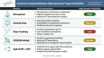
Key characteristics by method:
- Monopulse: Single-pulse error derivation, no scan lag, best for high-dynamics targets
- Conical scan: Periodic error signal, vulnerable to scintillation, scan-rate lag limits dynamic response
- Step tracking: Slow convergence, angular oscillation, suitable for low-dynamics or hover applications
- GPS/INS-aided: Open-loop predictive pointing, maintains track through RF dropouts
- Hybrid RF + GPS: Blends both sources for maximum robustness across all flight conditions
Core Components of a Real-Time Tracking System
Antenna and Pedestal
The pedestal provides two (azimuth/elevation) or three mechanical degrees of freedom and carries the antenna through its tracking arc. Key specifications to evaluate:
- Maximum slew/tracking rate (deg/s) — must exceed target's maximum apparent angular rate
- Angular acceleration (deg/s²) — determines how fast the servo responds to abrupt maneuvers
- Positional accuracy (deg RMS)
- Drive motor type — DC servo, brushless servo, or hydraulic for high-speed military applications
- Elevation range — Safran's SPARTE 500 covers -5° to +185°, handling near-overhead passes
Tracking Receiver and Angle-Error Extractor
The tracking receiver is the RF front end that produces the error signals driving the servo. For monopulse systems it outputs angle-error voltages; for conical scan it produces the amplitude-modulated error envelope. Key requirements:
- Frequency agility across IRIG-106 telemetry bands (L, S, C)
- High sensitivity and wide dynamic range to handle varying target range
- Programmable AGC and AM outputs with configurable time constants and filter bandwidths
Lumistar's LS-27-M Series tracking receiver covers 215 MHz to 6 GHz across standard aeronautical telemetry bands. It includes programmable AGC outputs (±5 VDC, ±1 dB linearity) and 32 selectable AM lowpass filters from 50 Hz to 50 kHz, with outputs designed to drive antenna pedestal control systems directly.
The compact LS-28-DRSM Series adds dual-channel diversity combining in a form factor small enough to mount at the pedestal or feed assembly.
Antenna Control Unit (ACU)
The error signals from the tracking receiver feed directly into the ACU, the real-time digital controller that closes the loop. It executes the tracking algorithm and issues servo drive commands. Key performance specifications include:
- Processing latency — determines servo responsiveness to fast target maneuvers
- Control-loop update rate — higher rates improve tracking stability under dynamic conditions
- Programmable gain — tuned to prevent hunting while maintaining angular lock
Orbit's AL-4000 ACU, for example, supports fast-target and dynamic tracking with an IP interface and clock synchronization.
Position Feedback Encoders
High-resolution angle encoders on each pedestal axis tell the ACU the antenna's actual pointing at all times. The Western Test Range's GKR-7 30 ft antenna uses 13-bit shaft angle encoders with 0.044° resolution, supporting its 0.1° RMS tracking accuracy specification.
Encoder resolution sets a hard ceiling on achievable pointing accuracy. No amount of control-loop refinement compensates for coarse position feedback.
Integrating Tracking with a Flight Test Telemetry Ground Station
Antenna tracking and telemetry data acquisition aren't separate problems — they share the same RF signal path and must be designed together.
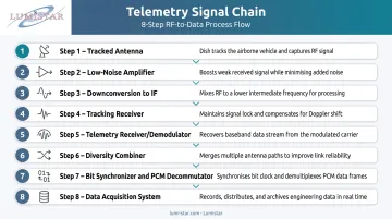
The signal chain from antenna to data output follows this sequence:
- Tracked antenna maintains beam alignment; receives RF energy
- Low-noise amplifier (LNA) at the pedestal preserves link margin before cable losses
- Downconversion to an IF (the Western Test Range converts L/S-band to 215–315 MHz for distribution)
- Tracking receiver extracts angle-error signals and feeds the demodulator input simultaneously
- Telemetry receiver/demodulator recovers the PCM or IRIG-compliant data stream
- Diversity combiner (pre-detection or post-detection) when multiple antenna feeds are used
- **Bit synchronizer and PCM decommutator** reconstruct and parse the data stream
- Data acquisition system records, displays, and distributes the telemetry
The ACU communicates with the ground station controller via standard digital interfaces. IRIG-106 documents RS-232, RS-422, Ethernet, and UDP/IP (port 10620) as standard options. Lumistar's LS-28-DRSM supports simultaneous Ethernet, USB, and RS-232 control independently, so antenna pointing status can be monitored and logged alongside flight data for post-mission analysis.
Lumistar's ground station product line — from the LS-28-DRSM receiver/combiner through the LS-68-M baseband processing system to the LS-29-R2 RF recording system — is built to IRIG-106 Class I and II standards and deployed at federal test ranges including the Western Test Range.
The LS-28-DRSM's dual-channel tracking receiver outputs integrate directly with pedestal ACUs. Its sub-1 kg modular form factor makes it practical to mount at the feed itself, minimizing cable-induced signal loss before the error signal is extracted.
Choosing the Right Tracking System
Method-to-Mission Framework
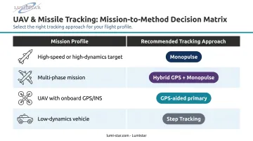
| Mission Profile | Recommended Approach |
|---|---|
| High-speed or high-dynamics target (missile, fighter, hypersonic) | Monopulse autotrack, GPS-aided fallback |
| Multi-phase mission with predictable segments + aggressive maneuvers | Hybrid GPS-aided + monopulse |
| UAV with onboard GPS/INS, reliable data link | GPS-aided primary, RF autotrack secondary |
| Low-dynamics vehicle, cost-constrained | Step tracking viable |
Specifications to Request from Vendors
Before procurement, confirm these specifications in writing:
- Maximum angular tracking rate (deg/s) and angular acceleration (deg/s²)
- Tracking accuracy (deg RMS) under rated conditions
- Tracking receiver frequency coverage and sensitivity (noise figure, input power range)
- ACU update rate and supported tracking algorithms
- GPS/slave mode availability and documented re-acquisition performance
- Environmental ratings: wind load, operating temperature, and humidity for mobile deployments
- Interface standards: Ethernet, serial, and analog output specifications
Integration and Support
Specifications get you to the shortlist. What determines actual field performance is gain tuning, calibration, and operator familiarity. A system that's improperly tuned will hunt, lose lock, or exhibit poor transient response even if every datasheet number looks adequate.
For mobile or custom range configurations, where the operating environment rarely matches factory test conditions, vendor support after delivery is not optional. Prioritize vendors who offer system-level integration assistance and operator training alongside hardware. Lumistar provides support from initial requirements development through post-delivery on-call assistance, which is directly relevant when integrating tracking pedestals with downstream data acquisition hardware across range configurations that are never quite the same twice.
Frequently Asked Questions
How is tracking a moving aircraft different from tracking a geostationary satellite?
Aircraft generate angular rates of 10–20+ degrees per second with unpredictable maneuvers, requiring high-bandwidth servos and active tracking methods like monopulse or GPS-aided pointing. Geostationary satellites produce near-zero angular motion, so simple programmed steering or step tracking is sufficient; servo bandwidth and tracking algorithm sophistication are largely irrelevant.
What tracking method works best for high-speed or maneuvering test vehicles?
Monopulse is the industry standard, supported by Western Test Range documentation and Safran's SPARTE 500 specifications. Its instantaneous angle-error derivation handles fast maneuvers that outpace a conical-scan system's update cycle, while GPS-aided pointing maintains beam alignment during brief fades until RF autotrack re-acquires.
What angular tracking rate should a flight test pedestal support?
Documented examples range from 10 deg/s for large fixed-range antennas to 20 deg/s with 20 deg/s² acceleration for the Safran SPARTE 500. There is no universal requirement — the correct specification depends on target velocity, minimum slant range, and maximum elevation angle during the mission. Calculate the worst-case apparent angular rate from your trajectory geometry, then add margin.
How does GPS-aided tracking improve real-time performance?
GPS/INS data from the aircraft drives open-loop pointing commands ahead of any RF error signal, eliminating detection and processing latency. The antenna stays aligned through signal outages, multipath fades, and maneuvers that break RF lock, cutting re-acquisition time and protecting data-link continuity.
What causes an antenna tracking system to lose lock?
The primary causes include:
- Target exits the pedestal's mechanical scan volume
- Signal fade from multipath, terrain masking, or airframe shadowing
- Target angular rate exceeds the servo's maximum tracking rate
- RF interference or jamming corrupts the angle-error signal
GPS-aided tracking mitigates the first three. Interference requires range coordination and receiver filtering to address.
How does antenna tracking integrate with a telemetry data acquisition system?
The tracking receiver processes the RF signal to extract angle-error data for the servo while feeding the same signal to the telemetry demodulator. The ACU communicates pointing status and mode commands to the ground station controller over standard interfaces (Ethernet, RS-422, or serial), allowing pointing data to be logged and time-correlated with the flight telemetry stream.